
Revolutionary Machining Tech | 'Skip Tooth' Finish
Our 'Skip Tooth' tech allows us to control what parts of a component we want to chamfer. Instead of running a whole edge, this operation can 'skip' over the part that doesn't need a chamfer…
Our 'Skip Tooth' tech allows us to control what parts of a component we want to chamfer. Instead of running a whole edge, this operation can 'skip' over the part that doesn't need a chamfer.
We can also program other motions and tools into this operation. Whatever your imagination can think of, we can do with our 11-axis MAX Systems machine.

The Difference Between Grinding, Polishing, and Deburring
These three machining processes all seem frustratingly similar—so what makes them different from each other?
Grinding, polishing, and deburring—anybody who knows anything about the precision machining process knows that these three processes are a.) crucial, and b.) acts of surface finishing. These three processes are very similar to each other, and for decades have been making people ask the same questions: What’s the difference? And why do we need to do all three processes? Both of these questions are valid, and we have the answers to both below.
The difference between grinding, polishing, and deburring.
1. Grinding
This is the process of removing material and shaping a workpiece into its final form. Grinding can be done on a multitude of materials, such as plastic, ceramic, and many different metals (stainless steel, titanium, high-nickel alloys, etc.). In order to complete this process, grinding wheels of different abrasives are used in various machines made specifically for grinding. It’s important that the correct kind of abrasive is used, as too soft of an abrasive can’t grind a workpiece enough, while too hard of an abrasive will damage a workpiece and result in decreased part quality or scrapped part. Overall, grinding is essential because it improves a part’s surface finish, which not only provides the aesthetic many industries require, but also ensures the removal of pesky surface imperfections.
2. Polishing
Polishing is the process surface finishing, which is also known as the process of improving surface quality. Using softer, smaller abrasives like polishing compounds and wheels, surface imperfections such as scratches and unwanted film/layers are removed to achieve a part’s desired texture (as different industries require different surface finishes). Polishing can be done by hand, machine, or robot, as it doesn’t require quite as much precision as grinding or deburring do. This step can be taken farther with buffing, which gives parts a finish similar to that of a mirror.

3. Deburring
This process is the act of removing burrs from a part’s surface. Burrs are extra bits of metal that form as a part is being cut, and can be extremely harmful both for a part’s functionality and the overall assembly it’s a part of. Deburring can be done by hand or in a machine, though hand deburring proves to be inconsistent and costly. The process of deburring requires extreme precision, as any leftover bit of metal can cause inconsistencies that result in the decrease of a part’s longevity and efficiency. Deburring is required for any part that has been previously machined and can be done on a variety of different materials, such as ceramic, stainless steel, wood, titanium, and more. What makes it an essential process is it ensures parts meet industry standards and helps reduce the possible formation of stress risers.
Surface Profiling
Seeing as all three of these processes fall under surface finishing, it’s important to know how surface finish is measured. Surface profiling is the measurement of a surface’s roughness, which allows manufacturers to know how adequately prepared a part is for further processing, especially when it comes to the part coating and assembly stages. A profilometer is the tool used to measure these surfaces and can be split into two categories: contact and non-contact. Contact profilometers use a stylus to map out the highs and lows of the surface (also known as peaks and valleys) which allow operators to gauge how smooth or rough a workpiece surface truly is. A non-contact profilometer uses image sensors to detect a surface’s texture. While this is the faster of the two profilometers, it’s extremely sensitive to any dirt or oil that may be coating a part’s surface.
Why does manufacturing require all three processes?
Ultimately, grinding, polishing, and deburring are all needed for the same reasons: dimensional accuracy, part efficiency, corrosion resistance, and improved functionality. All of these processes refine parts so they’re safe, functional, and meet industry standards. In other words, it’s the manufacturing equivalent of editing a piece of writing before publishing. A part might work fine enough after it’s just been cut, but without grinding, polishing, and deburring, it probably won’t fit into its assembly correctly, and it certainly won’t reach its ultimate level of efficiency and precision. The time and energy spent on these three process ensure that overall assemblies will require less maintenance, which saves operators and businesses precious time and money.

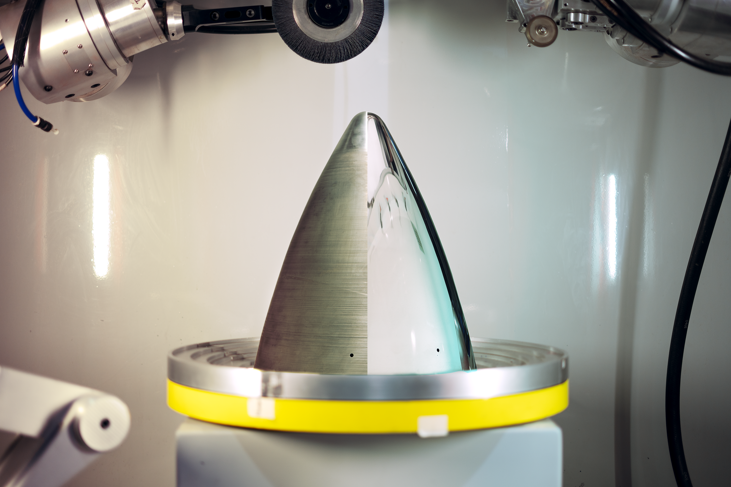
The Machine that can do it all
One of the most efficient ways of grinding, polishing, and deburring on the market is by using the MAX, an all-encompassing finishing machine sold and manufactured by James Engineering. This deburring and chamfering machine is capable of carrying out all three process concurrently. This means a part can be deburred, ground, and polished in one go. This machine also has a consistent precision unreachable by any hand-done method or other machine. The MAX makes all three processes easy and affordable, which ultimately revolutionizes any operation.
To watch the MAX in action, check out the James Engineering YouTube channel here.
To inquire more about the MAX, call (303) 444-6787 today.
What Is Gear Chamfering?
In simple terms, gear chamfering is the process of cutting a 90-degree edge at a 45-degree angle, but in reality it’s a bit more complicated than that.
Simply put, the process of chamfering is cutting a 90-degree edge at a 45-degree angle as a way to remove stress-rising sharp edges, as well as allow for smoother assembly. That makes chamfering sound easy, when in reality it’s actually very time consuming, no matter the method of approach.
Gear Chamfering can truly be broken down into four separate surface-finishing processes: deburring, chamfering, radiusing, and radius-chamfering.

- Deburring is the process of grinding off burrs, which are bits of excess metal created in the metal cutting process. Burrs are extremely problematic and will cause issues in assembly as well as overall part efficiency. Assuming the deburring has been done properly, all burrs will have been completely removed, leaving nothing but a sharp edge.
- Chamfering, as stated above, is the process of cutting that sharp edge at a 45-degree angle (which is the most common angle, but not the only one they’re limited to). Chamfering can be done with a myriad of tools, such as brushes, sandpaper, grinding wheels, and Scotch-Brite. However, in the process of shaving down this one sharp edge, two more are created on either side of the original, and if the tool being used is worn down, burrs can be created as well.
- Radiusing is the process of completely rounding out edges until it’s completely smooth. While chamfering is smoother than just leaving a part deburred, it still is cut at a noticeable angle that can be seen and felt. Radiusing feels and looks rounded (just like how a ball is round without any hard edge), and can also be carried out via brushes, grinding wheels, and sandpaper. It’s crucial to know what materials these tools are made out of, because the materials will affect the quality of the radius; if a material is too abrasive, it will be impossible to reach a true radius. A true radius is when the edges of a 90-degree angle go tangent to tangent without any surface imperfection.
- Radius-chamfering is when a part receives both radiusing and chamfering. The sharp angle is cut at the usual 45-degree angle, and when those two extra sharp angles are created, they are radiused to create smooth transitions between chamfers.
When it comes to how chamfering is done, there’s a few methods operators can choose from—machine-based, hand-based, or robot-based.
Different types of gear chamfering machines are capable of different sub-categories of chamfering. For example, a CNC machine can decently deburr a part, a lathe can adequately radius-chamfer a part, and a mill can chamfer a part. All of these options are valid, but not a single one of them can chamfer, deburr, and radius a part; separate machines are needed. Not only that, but these kinds of machines require in-depth programming for every single part in order to be exact. The MAX by James Engineering is capable of carrying out all four chamfering processes with heightened precision, as well as little programming.
Doing any of these processes by hand is technically achievable, but it ultimately proves to be more troublesome than it’s worth. Manufacturing is an industry that requires precision, as things will fall apart and fail to work correctly without it, and doing these processes by hand simply does not provide adequate enough precision. Even the best operator can slip or tremble, and man cannot repeatably guarantee a consistent chamfer. Hand chamfering is acceptable in a pinch, especially if only one or a handful of parts require it. But for higher volume operations, not only does hand chamfering not produce consistent results, it also is extremely time and cost inefficient. Scrap rates are the highest with hand chamfering, and the time it takes operators to complete one part is what it would take a CNC to do two or three, or the MAX to do a hundred.
Robots are only slightly better at gear chamfering than when done by hand. While they do have better mobility than most machines, they lack precision. Robots are perfect for operations that require the moving and placing of items, but they just cannot match a machine’s precision. Robots also require a lot of laborious programming, overall making them a poor method of chamfering.

Out of all these methods, the MAX is hands down the most reliable and efficient. As an all-encompassing finishing system, it is capable of deburring, chamfering, radiusing, and radius-chamfering any part or gear, no matter its complexity. It does require some initial programming, but once a part/gear has been loaded in, the MAX will remember it for future use, meaning operators no longer have to manually input adjustments themselves (James Engineering calls these programs “recipes”). The MAX is also capable of repeatable precision down to the fifth decimal. For reference, the average human hair measures to .003 inches. The MAX can repeatably work down to .00001 inches, and even beyond that.
Precision in chamfering is key, because the less precise a chamfer is, it’s more likely that stress risers will appear with continual usage. Stress risers are tiny cracks that form at a part/gear’s weakest point of contact (like the tooth on a gear). If a part is not adequately deburred or chamfered, what will happen is those sharp edges will slowly break off until a part or gear’s structure is ultimately compromised. So that previously mentioned tooth could fall off, for instance. That is extremely dangerous, both for the assembly itself and the people operating it. For example, a helicopter would crash if one of the gears in its motor failed. When it comes to chamfering, the higher the precision, the better. The precision achieved by the MAX means that parts/gears processed through it are extremely unlikely to form stress risers even after years of use.
There’s a misconception about chamfering that it’s done easily. Even with an advanced machine such as the MAX, chamfering is no “easy” feat. If a chamfering operation appears to be “easy”, it’s probably being done sloppily and inefficiently—and precision takes time and effort.
Knowing the correct way to chamfer is a gamechanger with any operation, as well as being able to recognize when a chamfer is done correctly. If it is, parts will fit together with no resistance and work efficiently for the entirety of their lifetime. And when parts work correctly, overall assemblies will perform at their best.
To visibly see how chamfering is done, watch a short video clip here.
To contact James Engineering about the MAX’s chamfering abilities, call at (303) 444-6787
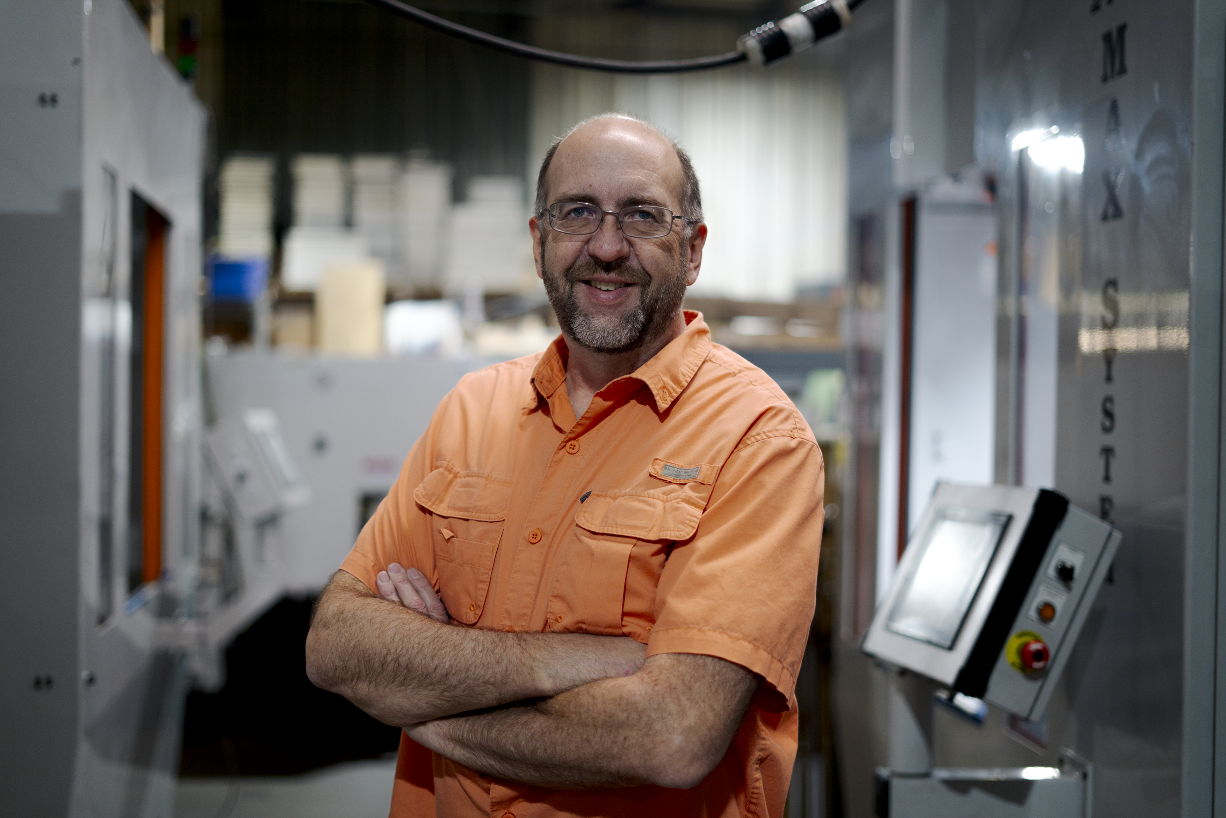
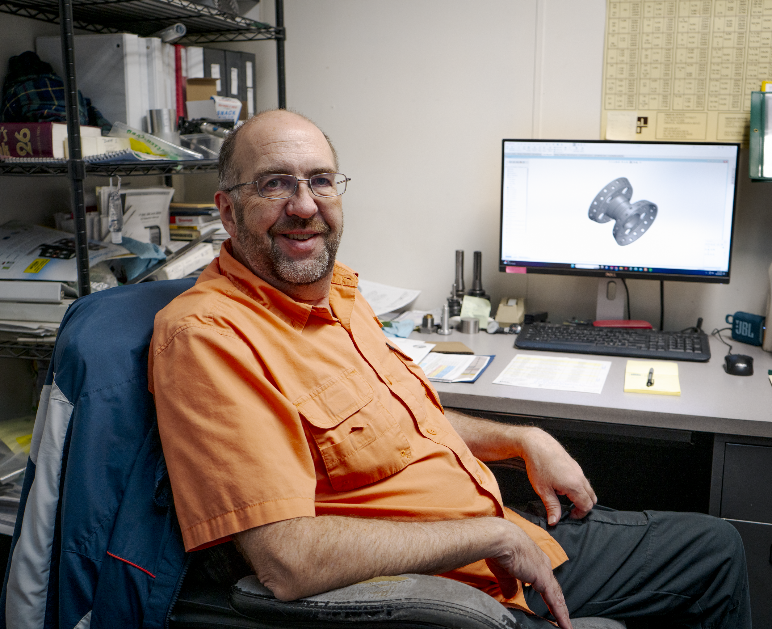
Innovating Tomorrow
James Engineering’s own Dave Schlosser gives us a sneak peek into his career as a mechanical engineer.
Within the walls of James Engineering, a dedicated engineer works tirelessly to perfect vital components and assemblies. Dave Schlosser, head engineer for the Coloradoan OEM shop, and his crew of engineers team up to draw, assemble, and manufacture the one-of-a-kind deburring machines sold by James Engineering. But Schlosser’s career in engineering began way before he joined the J.E. family.
“I started when I was 13 in my dad’s garage; he welded, so I’d help him with welding. Then I wanted to be a machinist because my dad was one,” Schlosser states. He got his foot in the industry’s door early, which eventually nudged him to go to school for machining. Eventually, he dipped his toes into quality control before migrating into the engineering department for a different company, which was eventually bought out.
After years of completing personal projects, such as an adapter plate for his Volkswagen transmission, Schlosser realized not only was he a talented engineer, but a creator at heart. So when he found his job at James Engineering, he knew it would be the perfect position to nurture his creative desires. Schlosser gives a little insight as to what his daily tasks consist of:
“I lead the engineering team. We got a couple of interns and full-time guys. I’ll also run what goes through the machine shop and help prioritize [the projects].” When asked how the position keeps his creativity flowing, he explains, “We do drawing revisions, part revisions, and new product development.”
Updating assemblies and part drawings is crucial—this process ensures that both the engineering department and shop floor are on the same page before pieces/assemblies are completed. Concise drawings create clear communication between the two groups, which ultimately does three things: decreases the number of errors made in production, increases shop efficiency, and allows for the creation of new products. Schlosser is central to this procedure. “We started making our own cogged pulleys,” Schlosser explains, “Belt pulleys, not like gears. [These] pulleys have slots in them for grooved belts. It’s like a timing belt in a car, which has little cogs in them. This eliminates backlash in our machines. We just started doing these about six months ago.”
While this process gives Schlosser the outlet he’s always wanted, it has proven to be the biggest test for him during his time at James Engineering. “Because we are a small company, there’s a lot of tribal knowledge of how things work. It’s not quantified in a lot of cases in drawings, so that’s a big challenge—getting that knowledge from somebody’s head and getting it put [on paper].”
Despite its trials, this shared knowledge is one of the most unique parts about working at James Engineering. “There’s tech here that you don’t see anywhere else. And Jim’s got [decades] of knowledge, so I learn from him every day.” Jim Richards is the founder of the company and works closely with the engineers every day. “I take what I know and keep adding on to that.”
Schlosser has collected new information and experience throughout his whole career. The mechanical engineering industry has only continued to evolve, introducing new technology and methods to its workers at astounding rates. “When I first got into the industry, CNC machines were brand new. Now, everything is computer controlled instead of being done by hand,” Schlosser reflects. With CNC machining giving manufacturers the upper hand in efficient and speedy production, engineers such as Schlosser can turn all their ideas into reality. ‘There’s a lot of stuff I want to develop with the tech here. Jim and I talked about building a table with our gantry system where you can plug in a router and a laser. This would be used instead of having multiple machines that do the same thing. I also want to do a whole series of our own products that don’t even necessarily have to do with deburring.”
With new waves of engineers pouring into the industry every year, mechanical engineering will further evolve. Schlosser offers them his seasoned advice: “If you’re going to be a mechanical engineering designing mechanical parts, learn machining! You don’t have to be an expert at it, just know how to make parts because then you can make drawings a lot faster. Go get a job at a machine shop just so you can learn how materials are cut. With experience like that, you’ll be years ahead of your peers who also just got out of school.” As somebody who worked in a machine shop before entering the engineering field, Schlosser knows firsthand how effective this method can be. “Learn how whatever you’re working on is made, whether it’s plastic, metals, etc.”
The mechanical engineering field is one that provides countless learning opportunities, and Schlosser cannot stress enough how important it is to take each one you can get your hands on. By doing so himself, he has worked a plethora of jobs that have built upon his knowledge every day. Schlosser’s time at James Engineering has not only taught him about hydraulics and pneumatics, but it has strengthened his abilities to problem solve and lead a team. Schlosser is coming up on his third year at the shop, and is given the freedom to do what he loves best—create.
“It all comes from your head, and then it’s in your hands. That’s what’s really cool about mechanical engineering.”
A cool career, indeed.

The Matter of The Sprocket
Sprockets can be tricky to deburr, but James Engineering has come up with the perfect solution.
Sprockets are an extremely common and useful gear used in everyday applications, such as bicycles and motorcycles. Some of the earlier automobile models even used them, taking inspiration from the mechanics of bikes!
A sprocket transmits rotary motion by locking its many teeth into a chain and driving it and therefore moving any other parts also connected to said chain. Sprocket gears can have multiple strands, meaning they can attach to multiple different chains at once, and have anywhere from 17 to 114 teeth. Anything above or below those numbers are inefficient.
Sprockets can either be made with or without hubs. Hubs are the thickness seen on either face of the sprocket and are separate from the teeth. The thicker the hub, the more torque the sprocket can transfer.
There are a few types of sprockets, each needed for different applications:
· Type A: These are flat with plain bores. This means they have no hubs at all.
· Type B: These sprockets have only one hub on one of their faces.
· Type C: These have two hubs, one on each face of the sprocket, and they are both equal in their thickness.
· Type D: These sprockets also have two hubs, one on each of its faces, but one is thicker than the other, offsetting it just like a Type B sprocket is offset.
If the wrong kind of sprocket is used (i.e. if its hub is too thick to fit snugly against equipment, or if its number/thickness of teeth don’t match with a chain’s tooth pitch), the entire chain assembly can fall apart, or cause time and money consuming shutdowns.
Sprockets pose a unique challenge when it comes to finishing them properly.
These big-or-little gears require intense attention to detail, which is vital for their function, but time consuming and costly. Normally, a sprocket would have to be deburred, chamfered, and brushed by hand or in a manual machine. These options are fine in some scenarios, but for a production business, these options will ultimately slow you down and disrupt the flow of operations.
A machine such as the MAX System greatly outpaces any manual and hand operations, especially when sprockets are involved. The MAX will process a sprocket of any size in up to 10 seconds. Two major features of the MAX allow for this amazing processing time: its capabilities to run multiple tools concurrently, and its ability to program part adjustments for future use.
The recipe programming of the MAX singlehandedly makes it a standout machine. It will take operators anywhere from 5 to 10 minutes to adjust the machine to a specific part, and once they have, the MAX will remember said adjustments and save them for future use. It can save a multitude of different part recipes, making it ridiculously easy to change out parts, no matter how drastic size differences/requirements are between them. Because sprockets are such tricky parts, this saves businesses an abundance of precious time.
The MAX also offers both wet and dry options. The machine will run beautifully either way, so it’s ultimately a matter of preference. However, the wet option is fantastic if you’re worried about flammable debris and how it can affect your machine. The wet MAX comes with rust-inhibiting solution so as to not damage machine or part, and it quickly washes away any debris before it becomes an issue. No debris will ever get caught between the teeth of sprockets of any size.
Sprockets can be a manufacturer’s nightmare, but they don’t have to be. The MAX System by James Engineering is built with efficiency and precision in mind, meaning it can take any sprocket with ease.
Watch the video below to see how all of this works in real-time.
High speed precision deburring for quick production

Happy Manufacturing Day!
Today is National Manufacturing Day, and the beginning of Manufacturing Month! Let’s dive in to the holiday’s history and importance.
Manufacturers! Hold your tools high, wear your grease stains with pride, and celebrate all your hard work, because today is National Manufacturing Day, and October is Manufacturing Month!
Didn’t realize that Manufacturing Day is a national holiday? It’s okay—it’s a relatively new holiday, as it was first declared on October 12, 2012. Only eleven years of celebrating an industry that has shaped America for hundreds!
The idea of Manufacturing Day was created back in 2011 in Rockford, Illinois, (but was officially recognized in 2012) as a way to break the industry’s stigma of hostile environments and labor-intensive work. The ultimate goal of the holiday is to shed light on how innovative and exciting manufacturing actually is, especially with the advanced technological skills and tools that have spurred the evolution of the industry, such as robots, computers, CNC machines, and more.

The manufacturing industry is one of the leading 10 industries in the United States, supplying 8.41% of the national workforce with jobs all over the country; that means roughly 12.5 million people work as or for manufacturers every year.
In 2021, 149,000 people worked for manufacturing companies in Colorado alone, making up 5.36% of the state’s workforce. Yet even though the industry is one of the tops in America, the growing shortage of trained workers has begun to affect the industry, leaving big gaps of unfilled positions.
These gaps then increase production time, lower company efficiency, and stunt industry advancement, which is why the breaking of stigmas and installment of internships and in-house training programs have become so crucial for recruiting the new generation of workers.
Here at James Engineering, we highly value learning opportunities and internship programs. Teaching the younger generation of manufacturing engineers about the industry advancements has been crucial for setting the stage for our future as a company, as well as their futures as individuals in the workforce. We provide our employees and interns with as much hands-on experience as possible, and we work together as a team to navigate the ever-changing world of manufacturing engineering. In Colorado, the top growing sect of the manufacturing industry is aerospace product and parts, which is what James Engineering, a Colorado-based company, has specialized in since being founded in 1980. We have become experts when it comes to aerospace part finishing, so much so that every plane in the sky has been touched by one of our machines. We know what it takes to succeed in the manufacturing industry, and we pass on our knowledge to those who are dedicated to further advancing our innovations.


Today it’s important to reflect on the impact the manufacturing industry has had on not only America, but the entirety of our world. The ever-developing industry has supplied millions of jobs to millions of people, and without these people, our planet would be a completely different place. Cars, airplanes, cellphones, medical equipment, even the clothes in your closet would cease to exist without manufacturing and all its astounding accomplishments. Here at James Engineering, we highly encourage those interested in the manufacturing industry to take any opportunity to learn more about its how’s and why’s, and to not be afraid to contribute their own original propositions. Manufacturing is no longer a dark-roomed, physically grueling industry that’s vicious on the body and mind—manufacturing is a technological, innovative industry nurtured by bright minds, inspiration, and passion.
For the rest of October, take a moment each day to observe the objects, equipment, and machinery around you that have been made possible by our world’s manufacturers. Take any chance you get to learn more about our mechanical surroundings, and push yourself to share your ideas with the world. You never know—you may be the next person to evolve the industry.


If you’d like to know more about the James Engineering impact, check out the rest of our website at https://www.james-engineering.com/. If you’re interested in joining our team, please send your resume or inquiries to Employment@James-Engineering.com, and we’ll get back to you as soon as possible!

Under (Air) Pressure
The air we breathe and the power it creates—how air motors work and why they’re preferred.
Air motors (or pneumatic motors) have been used in the manufacturing, industrial, and tooling industries for hundreds of years, of course evolving as the industries have changed. Nowadays, air motors can be sorted into three kinds: piston, rotary vane, and turbine. Here’s a breakdown of each type and how they work:
1. Piston motors utilize series of pistons that force feed compacted air down into a chamber, which is held open by a spring. When this air gets pushed deeper and deeper into the chamber, the spring is forced to bend. Once it has moved through the entire length of the chamber, the spring resets, and voila—rotary mechanical energy is created. These motors tend to move slower than the other two kinds, but they’re highly reliable, and are frequently found in hydraulic systems.
2. Vane motors are powered by a group of vanes that force chambers to expand open as they spin. As compacted air is pushed up against these moving vanes, it forces the motor to spin, which in turn creates the rotary energy. These motors can work quickly depending on what size they are, however they are known for working faster than piston motors. Vane motors are typically seen in natural gas engines, as the natural gas (as opposed to regular compressed air) is what applies the pressure against the vanes to make them move.
3. Turbine motors are small yet mighty, powered by air extension and velocity to create rotary energy (very similar to a turbine engine, which is where wind-generated energy comes from). These motors can be found in a lot of hand-held tools; even though they are small, they can spin at speeds up to 180,000 rpm and don’t add almost any extra weight to the tool.

What’s the benefit of using air motors?
There are a couple scenarios where air motors are preferable over electric motors.
For one, air motors don’t emit extra heat, which means they can work at a wide range of speeds without overheating. Air motors are much cheaper to replace than electric motors, and electric motors will overheat, resulting in a high-cost repair.
This also makes them safe to use in volatile settings. Since they don’t overheat, they won’t throw off any excess sparks that could possibly ignite any explosive vapors or particles.
Air motors are reversible. You might be thinking, but so are electric motors! You’re not wrong, but electric motors generate high levels of extra heat when reversed, and reversal will put unnecessary strain/shock on the equipment it’s running. Since air is compressible, it prevents all that extra strain and prevents any possibility of shock ruining equipment or disrupting load. So if air is suddenly reversed in an application, the air motor will simply reverse itself back.
Air motors are also compact when need be. Their tendency to be light weight also contributes to their lack of emitted heat, therefore making them even safer in explosive conditions.
James Engineering Air Motors
Here at James Engineering, we manufacture and sell a variety of air motors to fit needs of all different sizes and requirements. We offer both disposable and repairable motors at competitive prices that can be used in machining centers, robots, cobots, custom machinery, automation, and more.
Our air motors are precision machined at 1.75” diameter mounting surfaces, making them ideal for applications that rely on precise location and repeatability.

If you’d like to learn more about our air motors, please check out our air motors page; there you will find the specifications of each kind we offer.
If you are interested in purchasing one of our air motors, please reach out to Sales@James-Engineering.com, and we’ll work together to send you the perfect air motor for your operation.

No-Slip Grip
James Engineering Manufactures and sells grippers with unorthodox technology, reducing slippage and promoting efficiency.
What is a gripper? Well, just think about its name! Grippers are a device that allow robot arms to grab, hold on to, and move items, and are a key component when it comes to automatic assembly. Without them, parts couldn’t automatically be loaded in/out of machines, which is something that ultimately saves businesses a lot of money and time. For companies that process a high volume of items every day, an automatic machine is ideal; by the end of the year, an automatic machine will cost said company half of what it would’ve taken to hire an operator. These machines are essential for some businesses, but without grippers, they wouldn’t be able to function.
Grippers have a pretty simple function, but their structures and abilities can vary. Here at James Engineering, we manufacture and sell three main times of grippers: your standard gripper, a failsafe gripper, and a parallel gripper.

standard gripper
The standard gripper is one we’re all familiar with, as its arms open and close as air pressure is turned on and off.
These grippers are sturdy workhorses, but if there’s any malfunction with the air pressure, their arms will release whatever item it’s holding. This could potentially cost businesses a lot in damages, both for parts and the overall machine the gripper is inside.

failsafe gripper
James Engineering came up with the failsafe gripper as a way to combat heavy reliance on air pressure. Initially, operators will notice the failsafe gripper is powered by an air cylinder, but these grippers are actually made failsafe by internal coil springs.
These springs keep the arms of the gripper closed, even if air pressure were to fail. This ensures that neither part or machine will sustain any damage due to drops.

parallel gripper
James Engineering also manufactures a parallel gripper featuring technology unique to us. These grippers don’t swing open and closed like the aforementioned grippers, but instead slide on parallel axes. That means these grippers are perfect for picking up long, thin, or abnormally shaped items with ease. Your typical parallel gripper will have exposed tracks, making them very hard to keep dirt-free.
This contamination will ultimately wear down the gripper and create play in its arms. Play will make the arms bend, making them unable to keep hold of the items they need to grab. The difference in the James Engineering grippers is that they utilize a technology known as linear motion slides. These slides are not limited to grippers, but are a game changer when it comes to parallel gripper function. These slides allow the arms to roll on bearings, which squish dirt out of the tracks and prevent unnecessary wear. The bearings will also prevent play, so the lifetime of the James Engineering parallel grippers will outlast those of other competing grippers..
James Engineering believes in inventing the unorthodox, providing buyers with the most precise and efficient technology on the market. Not only are we deburring and chamfering machine manufacturers, we also manufacture items like grippers, as well as an array of other products. If interested in purchasing a gripper, or looking into what other products we offer, check out our PRODUCTS page.
But for now, get a grip and switch to a James Engineering gripper—we won’t let you slip!
Champion of Gear Chamfers
Achieving the perfect chamfer can be frustrating, as there are so many factors that could cause an uneven chamfer. James Engineering offers a couple of tips on how to become the champion of chamfers.
Getting a perfect gear chamfer is not easy. In many cases, many people aren’t even aware that it could be done better; they probably don’t even know why they aren’t seeing better results.
There are many variables that affect the outcome of a chamfer: grinding wheel speed, grinding wheel pressure, grinding wheel angle, rotary table speed, etc. Keeping all these components in mind can be a headache! Who knew such a process could be so complicated?
Well, James Engineering has a couple of tips that will help you achieve the cleanest chamfer possible:
· Make sure the grinding wheel engages the part gently. If it’s too quick in engaging, you might notice a small cloud of dust burst up from the point of contact, gouging the part in a way that is noticeable to the eye. This small cloud will contain 3 to 4 times more material removed in that single instant than what you’d see after chamfering the entire part!
· Be sure that the grinding wheel produces an even spark pattern. Any interruption in that pattern is a loss in efficiency, and can be caused when the wheel lifts and bounces back down onto the part. Whether that bounce is subtle or extreme, it will still cause a decrease in wheel life and leave you with an inconsistent chamfer.
· To eliminate heavy chamfer marks, or what we call striations, use a wheel that has natural shock-absorption, such as the wheel we sell at James Engineering. Most companies use rigid cutoff wheels made of fiberglass reinforcing material, bonded with a dense (and usually black) open-cutting resin. But we at James Engineering suggest using a reinforced open-cutting, resin-bonded wheel with shock-absorbing properties, which also happen to be a lighter color and won’t break when forced to flex slightly. The best way to see the difference between the two kind of wheels, other than overall performance, is to bounce the cutting edge of the wheel off your desk. The competing wheel will bounce instantly, while ours will absorb some of the impact’s shock and not bounce as wildly—it’ll even sound quieter!
If you implement these three tips, chamfering becomes a whole different animal. You’ll be able to hear the difference between a good and bad chamfer; the good will sound smooth, while the bad will sound choppy. You’ll be left with a chamfer so clean, so perfect, you won’t be able to help but call it the champion of all gear chamfers. If you have any questions, or would like to receive a wheel sample, please feel free to contact us at Sales@James-Engineering.com.

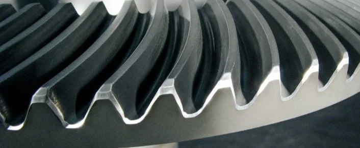
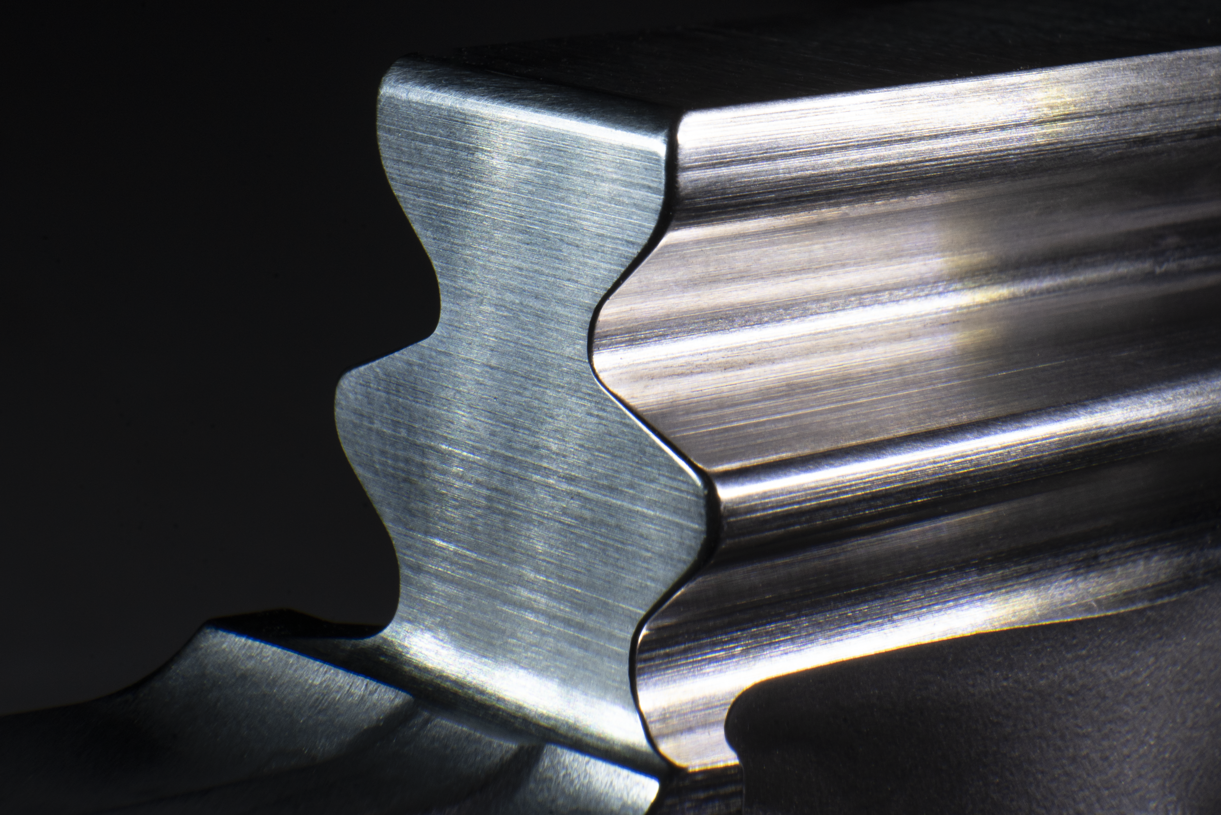
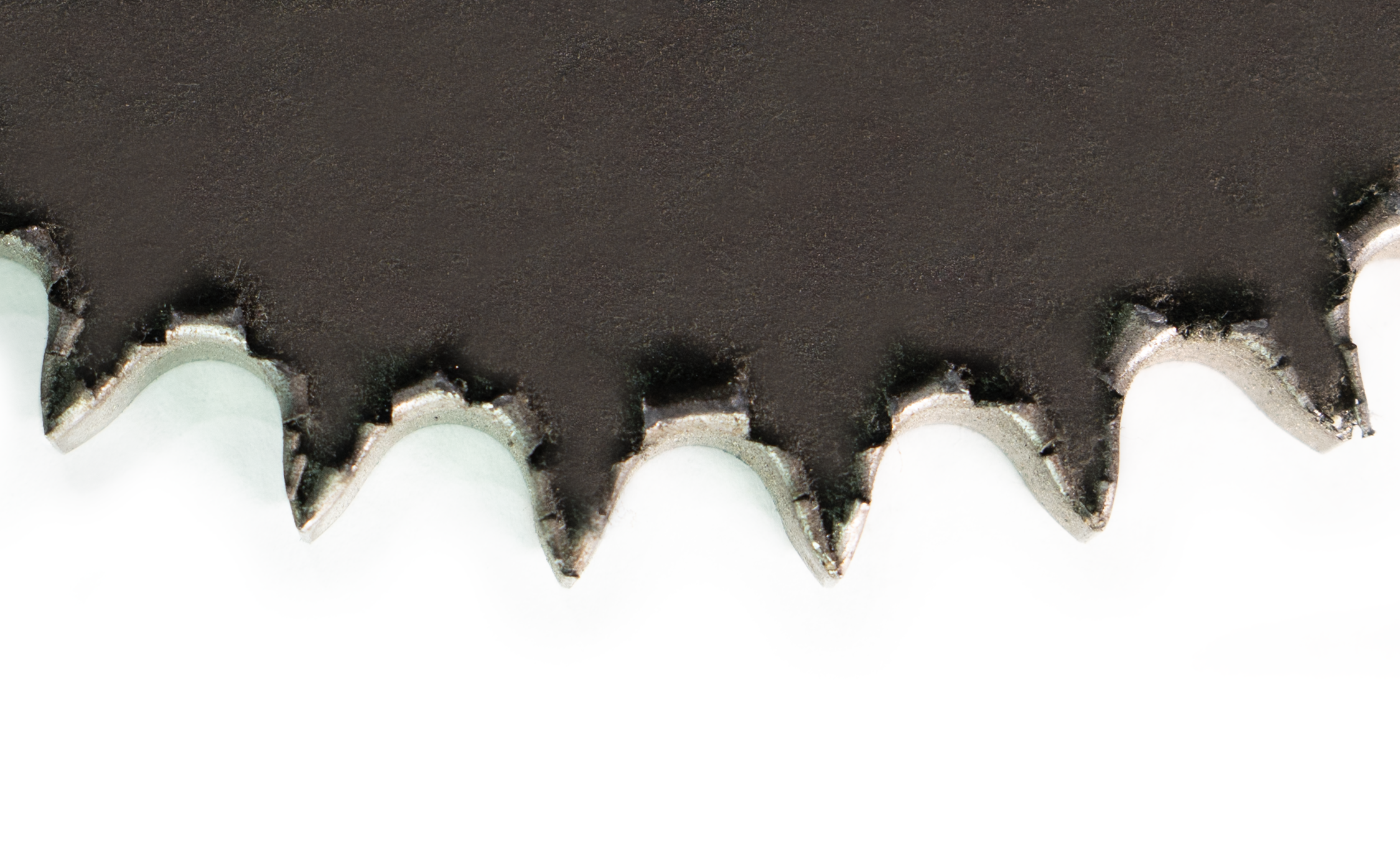
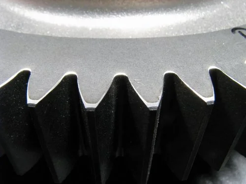
Rough, uneven chamfers.

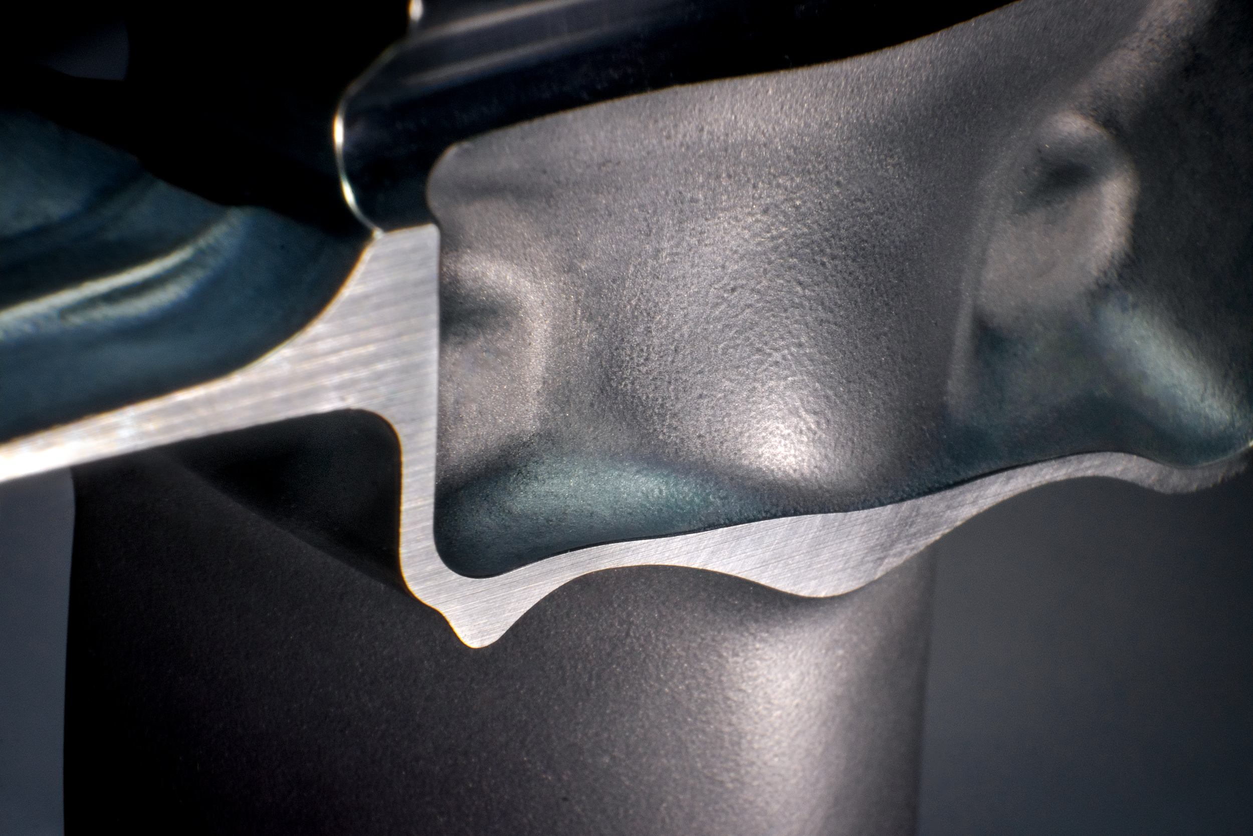
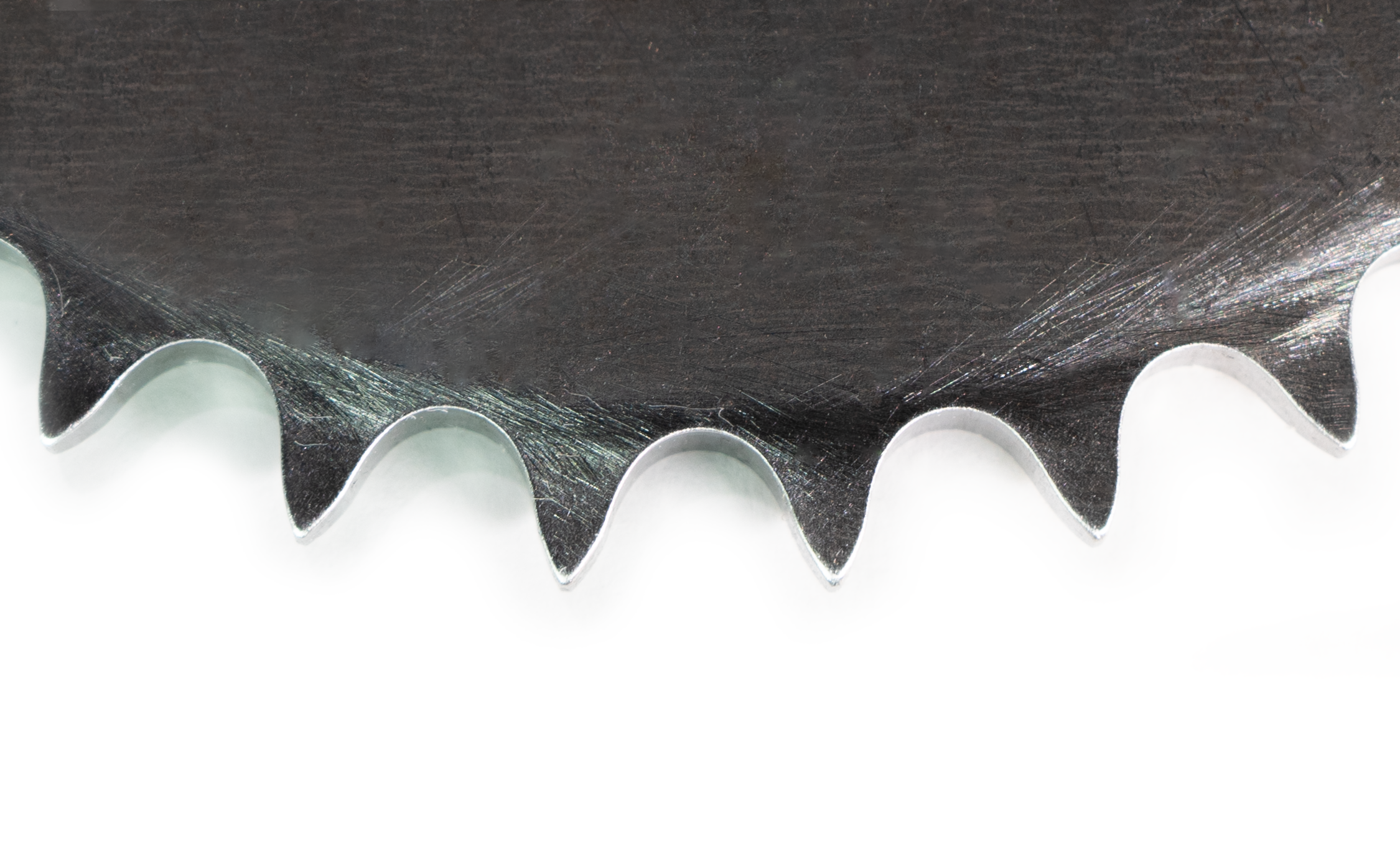
Smooth, even chamfers achieved by the MAX System, the ultimate gear chamfering machine