
Deburring Debunked: The Ultimate Challenges
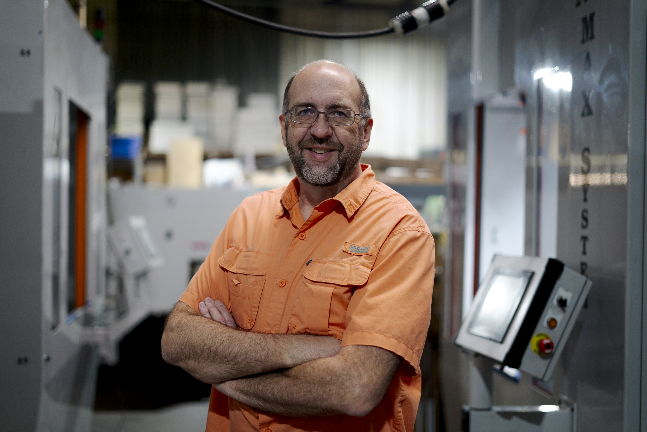
Jim Richards, founder of James Engineering, explains the top three part finishing challenges and the secret to overcoming them.
The process of finishing parts and gears before assembly comes with a set of its own unique issues. This manufacturing process is vital and cannot be skipped, or else assemblies would fail due to poorly prepared parts/gears. Finding simple, efficient solutions to these issues is crucial, as it ensures overall effectiveness and quality of an assembly.
We interviewed Jim Richards, the founder of James Engineering, and asked him what he finds to be the top three part finishing challenges. Richards has been at the forefront of the deburring industry for a little over forty years and is seasoned when it comes to overcoming a challenge.
1. Conflict with Customer Prints
“One of the biggest challenges is meeting customer requirements within blueprints,” Richards says. “Sometimes, the people writing these specifications don’t understand the tooling that is required with deburring or how it works.” Richards later goes on to say that this particular issue is not only the hardest one to solve, but the most common one faced within the deburring industry. The process of deburring is very complex, and if blueprints aren’t drawn correctly, deburring can seem impossible on that specific part because of the ultimate limitations that come with the process. “Sometimes we don’t have the kind of tools to do what the blueprints ask of us,” explains Richards, “but we’ve learned to solve these problems over the years.”
What Richards has learned is that collaboration and adaptability are key when it comes to sidestepping this conflict. The engineers at James Engineering are in constant contact with their customers in order to meet their requirements in achievable ways. “Sometimes we get companies who send in drawings that we absolutely cannot change,” Richards adds, “Take Pratt & Whitney for example. That’s a big company that requires consistency, we can’t just up and change what they’ve sent us. So we have to do what they’re wanting us to do. But we’ve learned to do the job.”
2. Cost of Consumables
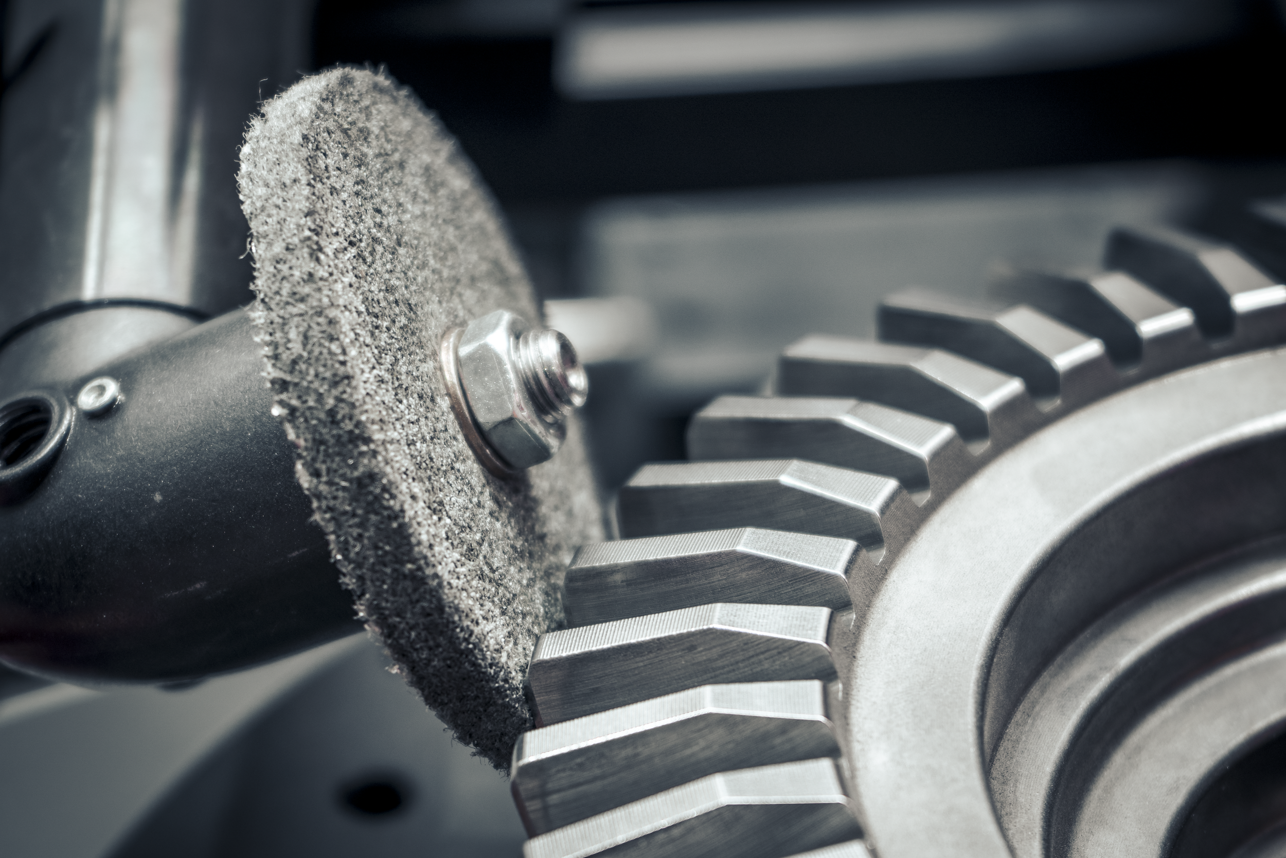
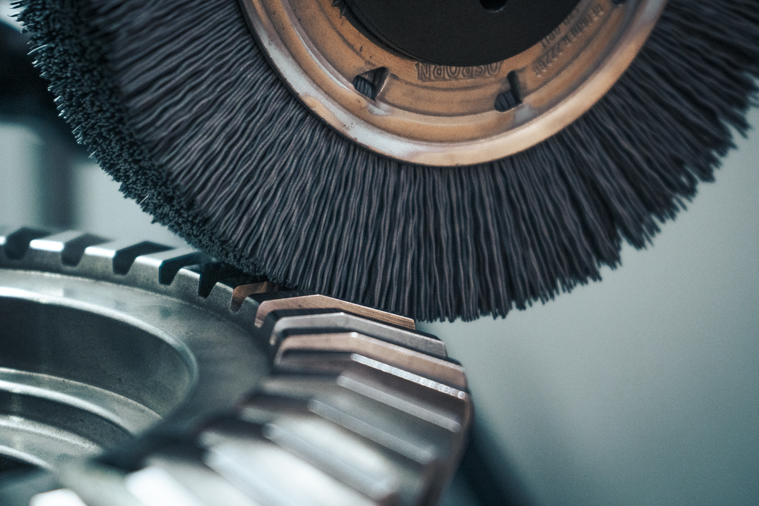
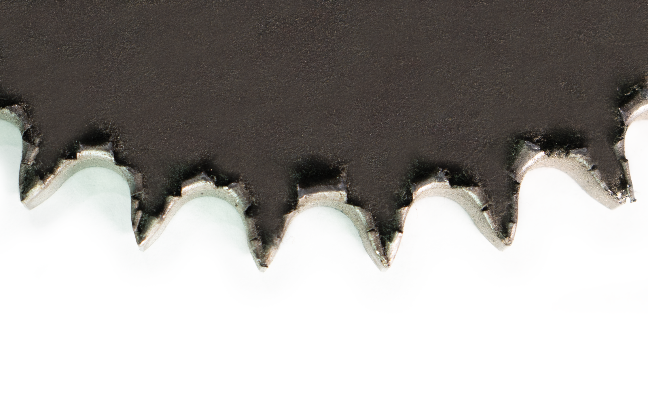
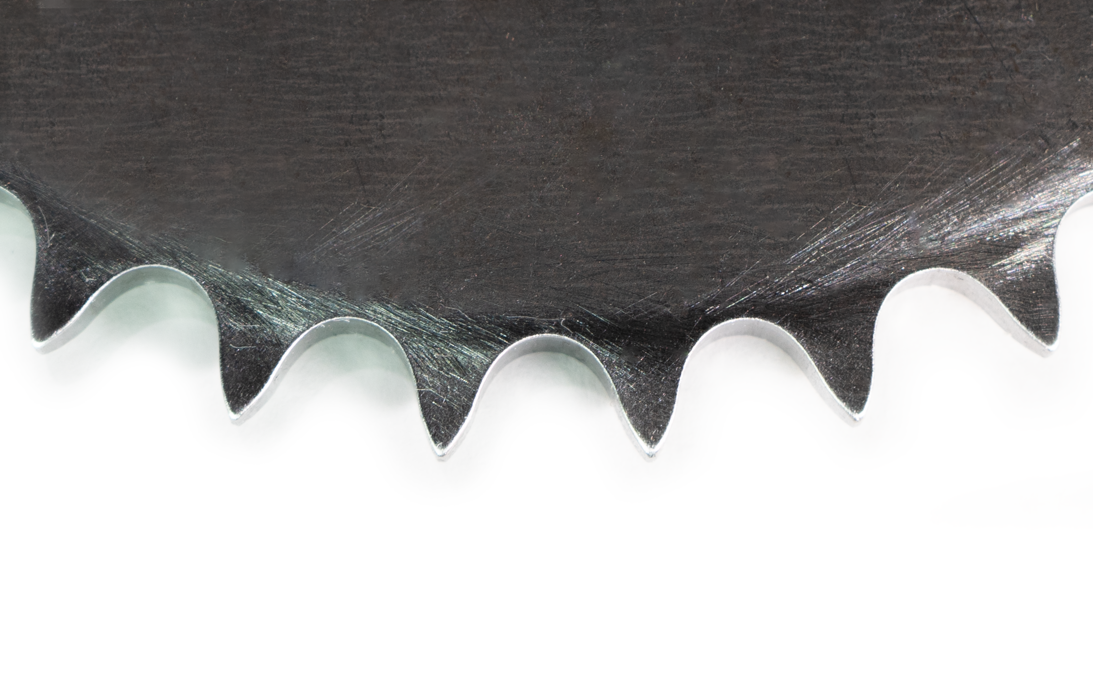
“Understandably, you can’t build a quality part with cheap materials,” Richards starts, “Sometimes you have to spend a little more to get a better part.” Richards explains that every James Engineering machine is built with the intention of using particular brands or items. If these specifications aren’t followed, the final quality cannot match what is promised by one of their machines. “The quality of chamfer we need and produce is from running a finer grit grinding wheel,” Richards explains when asked for an example. “The wheels we use are made of cotton, which don’t last as long as these tiger claw, aluminum oxide coarse wheels. Well, these coarse wheels remove metal fairly easily, but they leave a really jagged finish. People run these wheels for economic reasons, because yes, they’re cheaper, but they will destroy a part.”
James Engineering machines are known for producing beautifully precise and consistent chamfers. This is greatly due to the kind of grinding wheels they use, which are comprised of cotton and resin. The idea of using cotton in a grinding wheel is surprising to many, but in terms of chamfering, this kind of wheel is a champion of it. The cotton acts as a dampener, meaning these wheels’ tendency to bounce is extremely low, especially compared to woven fiberglass wheels. While the cost of running these coarse fiberglass wheels is smaller up front, it will actually cost a greater amount in the long run due to a high rate of scrapped parts. This is a great example as to why using the intended tools is extremely important for overall production. “We have to establish what we’re going to use and that has to be followed.”
3. Consistency of Parts Presented

The third most frequent challenge Richards has seen is the consistency of parts presented. “We often get sample parts from customers, and their conditions will sometimes change. So then we have to take samples of burrs and look at their size and decide what we can and cannot do. I’ve seen samples come in with burrs an inch and a half tall!” Essentially, machines are manufactured to handle a consistent, established size of burrs for specific parts. For example, a company will send in a dozen samples of the same part. Eleven out of twelve of these parts have burrs roughly the same size, but the twelfth will have a burr substantially larger than the rest. This twelfth part wouldn’t receive complete deburring using the same specs as the other eleven parts—it would require an entirely different set of measurements, tooling, and time. But this issue is easily avoidable as long as customers take care of one particular aspect: changing the part cutter on their CNC machines.
“When you’re making a gear or part, the hob cutter will start off as razor sharp, but it eventually wears out, naturally. We [at James Engineering] have to make sure we qualify when you change your cutter. Operators can’t be running their cutters down to total wear then give us huge burrs. So we need to establish the point of which they change their cutter so we receive parts that we’re capable of deburring.”
This may sound laborious and costly, but again, this ultimately saves money in the long run. If cutters are changed regularly, the predictability and consistency of their parts becomes manageable. This then makes it easier for James Engineering to manufacture machines that work perfectly for a shop’s needs. If the cutter is not changed frequently, extra tools must be added to a shop’s machine, costing them more in money and processing time. “You’re better off to change the cutter and leave our process simpler,” Richards explains.
So, how avoidable are these challenges?
“These are all very easily avoidable!” says Richards. “With consistency of parts presented, we just need to qualify the part that we’re going to deburr and establish that in writing. With the cost of consumables, we have to establish exactly what we’re using and write it into the warranty. Conflict with customer prints is always trickier, as we sometimes can’t change anything about the blueprints we’re sent. [We just] have to be adaptable.”
James Engineering prides itself on being a thorough and precise business—these values can be found at the core of the company. They are what make their machines so consistent and products so repeatable. There’s a reason why their deburring systems are at the top of the market.
What are the ultimate solutions?
With each customer comes a new challenge, but conflict with customer prints, the cost of consumables, and consistency of parts presented are usually given. However, after decades of dealing with the same issues, Richards and those at James Engineering have found that the following are the top solutions:
· Adaptability
· Reliability
· Flexibility
· Thoroughness
· Consistency
· Communication
By adhering to these six simple values, no challenge is too much for James Engineering.
To learn more about their machines, click here.
To send any sales inquiries or further questions, email Sales@James-Engineering.com
Types of Deburring
Let’s dive in to eight different methods of deburring!
Punch Deburring
Since its perfection in 1770, sheet metal has become a commonly used material within the manufacturing world. One of the most popular ways of cutting and manipulating sheet metal is a method called “punching”. A punch machine uses interchangeable tools to cut out shapes from the sheet metal, and it’s vital that these tools are sharp. If they aren’t, they require more force to cut through the metal, which can lead to the formation of burrs. Punch machines can deburr the pieces of sheet metal they just cut, and they do so with another set of interchangeable tools, which are meant for deburring. This method of deburring works well for pieces cut from sheet metal, but it’s extremely limited when it comes to parts with complex geometries.
Tumbling Deburring

This method involves parts/gears being tumbled in a barrel full of water and loose materials (known as tumbling media), such as glass beads, steel, or plastic. The force of the material and parts tumbling against each other will break off any present burrs and smooth out a part’s surface. Operators must be able to choose their media correctly, as some will do extreme damage to gears/parts made of other certain materials. For instance, steel parts must be paired with steel material. Tumbling is a good option for larger parts/gears, as it is a quicker way to remove their burrs compared to doing it by hand, and they are less likely to suffer overall structural damage from it. However, that risk is still there, and it can ultimately do more harm than good.
Vibratory Deburring
Vibratory deburring is like the tumbling method in the sense that parts are put into a barrel with tumbling media, but it’s more effective and gentler than its cousin method. When the loose material is vibrated against parts/gears, the force shears off burrs and other imperfections with equal force, making it a safe method for smaller, more delicate parts. This process is used frequently within industries such as the aerospace or medical industries and can even be used for parts made of wood or plastic.
Cryogenic Deburring
The cryogenic deburring method is similar to freezing off a wart. Parts are put into low-temperature chambers, where burrs are then frozen until brittle. The burrs will then get knocked off part surfaces when non-abrasive media is thrown into the chamber. This process doesn’t leave residue and preserves the surfaces of parts of any size. It’s a good option for processing large amounts of parts/gears at once, but it still lacks the precision that is necessary for complex parts.
Hand Deburring

This might be the most common—and the most time consuming—deburring method out there. Workers use handheld tools to manually complete processes such as brushing, edging, chamfering, polishing, and of course deburring. While this method allows for focused precision, workers are limited to working on one part at a time, making it extremely inefficient for high or medium volume shops. These workers also require adequate training and experience, seeing as one mistake can scrap an entire part; a little too much material taken off a part/gear can cause it to not fit into its greater assembly properly and affect its long-term efficiency. Another issue with hand deburring is that consistent chamfers are hard to achieve with it, and chamfers of poor quality will also affect the function of a larger assembly. Some manufacturers still prefer hand deburring to other methods, but it costs too much time and money to be used widely.
Electrochemical Deburring
Electrochemical deburring is a unique method of deburring that shoots currents of voltage between a cathode and a burr, ultimately dissolving said burr. This process can remove any sort of excess unwanted surface material. It’s important to maintain a gap between the cathode and part needing deburring, as this gap (paired with an electrolyte solution) allow for the transfer of voltage. It’s much more precise compared to methods such as punch deburring or tumbling deburring, and allows holes, cross holes, and intersections to be deburred easily. However, this method is limited to a small variety of materials seeing as some don’t contain the required levels of conductivity.
Thermal Deburring
The thermal deburring technique is carried out by placing parts in a pressurized chamber and setting off a series of controlled combustions, which essentially melt off any burrs or surface imperfections. The overall structure of the part/gear in the chamber isn’t harmed due to how momentary these mini explosions are, however the risk of excessive heat damage is still present. Once the burrs are removed, the part/gear is left with a thin film coating its surface and it must be cleared off before it is further processed. While efficient when it comes to removing multiple burrs/surface imperfections at once, it also lacks the necessary precision required by some industries, such as the aerospace industry.
Machine Deburring
Machine deburring is the most effective method of deburring when it comes to timeliness, cost efficiency, and precision, and has been gaining popularity as the demand for all three of these factors has grown dramatically over the course of the last few years. Machine deburring extends to both CNC machines and finishing machines, such as the MAX System from James Engineering, a high precision deburring and chamfering machine. CNC machines are most efficient when it comes to cutting parts, but they also have limited deburring capabilities. The MAX System and its one-of-a-kind technologies allows the machine to deburr and chamfer, radius, wash, and brush a part concurrently. This is due to its multi-tooling feature, which is customizable to any company’s needs. It also features an 11-axis overhead gantry system, making any angle reachable. The MAX is a great option for both parts and gears of any size and any complexity, and with Focused Deburring (a technology unique to James Engineering), burrs can be targeted—something only James Engineering finishing systems are capable of.
Which one is right for you?
These eight methods of deburring are used for a wide range of industries, parts, and gears, and each have their own pros and cons. Finding the right one for your company ultimately depends on the volume at which your shop is producing, and what parts/gears you produce. The lower your shop’s volume is, and the simpler your parts, methods such as hand deburring can be a reasonable choice. If your shop is producing at a high volume and working with a wide array of gears/parts of a variety of materials, a specialized finishing machine such as the MAX System is the most time and cost-effective move to make. Doing your own research is important, and you know your shop’s needs the best… but you can never go wrong with the MAX.
Innovating Tomorrow
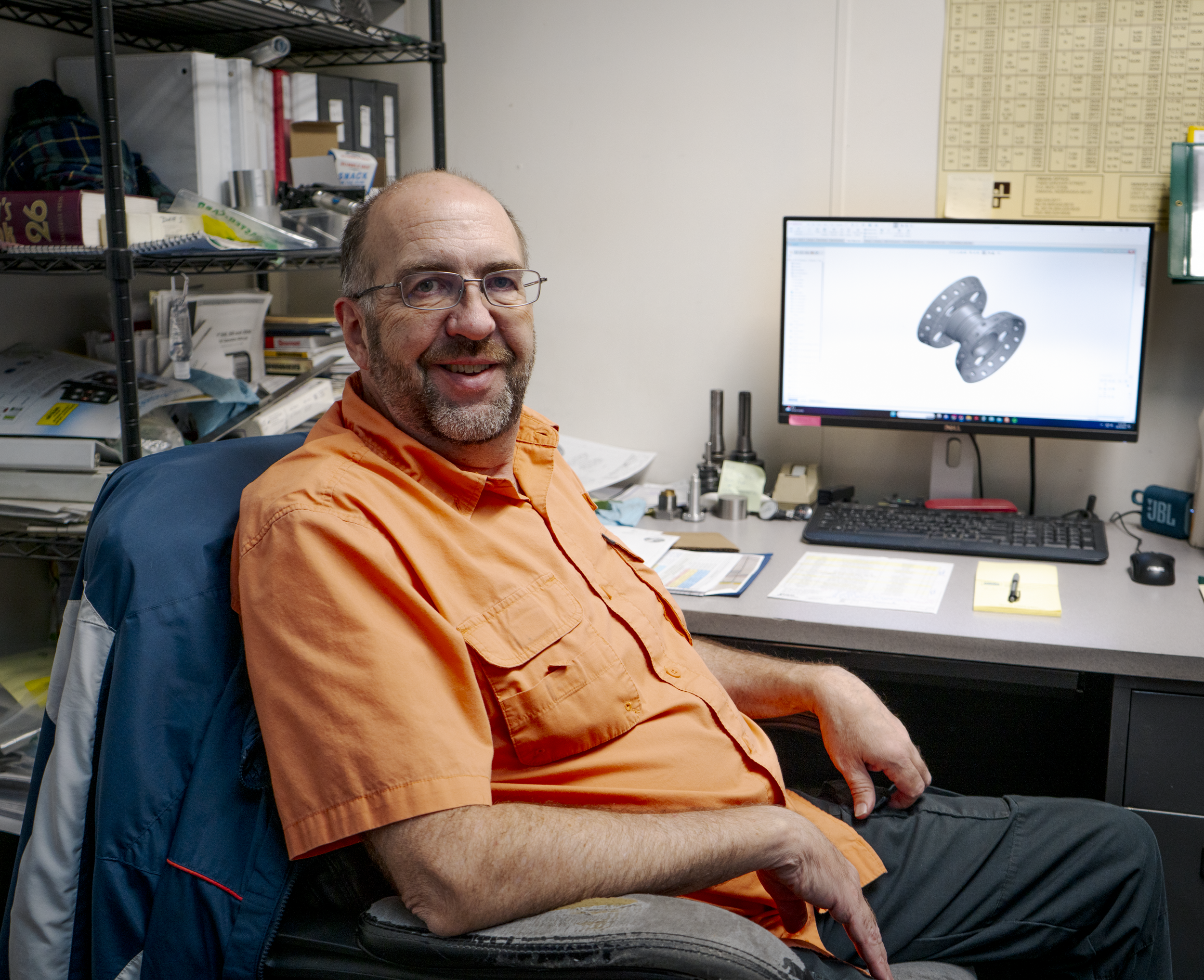
James Engineering’s own Dave Schlosser gives us a sneak peek into his career as a mechanical engineer.
Within the walls of James Engineering, a dedicated engineer works tirelessly to perfect vital components and assemblies. Dave Schlosser, head engineer for the Coloradoan OEM shop, and his crew of engineers team up to draw, assemble, and manufacture the one-of-a-kind deburring machines sold by James Engineering. But Schlosser’s career in engineering began way before he joined the J.E. family.
“I started when I was 13 in my dad’s garage; he welded, so I’d help him with welding. Then I wanted to be a machinist because my dad was one,” Schlosser states. He got his foot in the industry’s door early, which eventually nudged him to go to school for machining. Eventually, he dipped his toes into quality control before migrating into the engineering department for a different company, which was eventually bought out.
After years of completing personal projects, such as an adapter plate for his Volkswagen transmission, Schlosser realized not only was he a talented engineer, but a creator at heart. So when he found his job at James Engineering, he knew it would be the perfect position to nurture his creative desires. Schlosser gives a little insight as to what his daily tasks consist of:
“I lead the engineering team. We got a couple of interns and full-time guys. I’ll also run what goes through the machine shop and help prioritize [the projects].” When asked how the position keeps his creativity flowing, he explains, “We do drawing revisions, part revisions, and new product development.”
Updating assemblies and part drawings is crucial—this process ensures that both the engineering department and shop floor are on the same page before pieces/assemblies are completed. Concise drawings create clear communication between the two groups, which ultimately does three things: decreases the number of errors made in production, increases shop efficiency, and allows for the creation of new products. Schlosser is central to this procedure. “We started making our own cogged pulleys,” Schlosser explains, “Belt pulleys, not like gears. [These] pulleys have slots in them for grooved belts. It’s like a timing belt in a car, which has little cogs in them. This eliminates backlash in our machines. We just started doing these about six months ago.”
While this process gives Schlosser the outlet he’s always wanted, it has proven to be the biggest test for him during his time at James Engineering. “Because we are a small company, there’s a lot of tribal knowledge of how things work. It’s not quantified in a lot of cases in drawings, so that’s a big challenge—getting that knowledge from somebody’s head and getting it put [on paper].”
Despite its trials, this shared knowledge is one of the most unique parts about working at James Engineering. “There’s tech here that you don’t see anywhere else. And Jim’s got [decades] of knowledge, so I learn from him every day.” Jim Richards is the founder of the company and works closely with the engineers every day. “I take what I know and keep adding on to that.”
Schlosser has collected new information and experience throughout his whole career. The mechanical engineering industry has only continued to evolve, introducing new technology and methods to its workers at astounding rates. “When I first got into the industry, CNC machines were brand new. Now, everything is computer controlled instead of being done by hand,” Schlosser reflects. With CNC machining giving manufacturers the upper hand in efficient and speedy production, engineers such as Schlosser can turn all their ideas into reality. ‘There’s a lot of stuff I want to develop with the tech here. Jim and I talked about building a table with our gantry system where you can plug in a router and a laser. This would be used instead of having multiple machines that do the same thing. I also want to do a whole series of our own products that don’t even necessarily have to do with deburring.”
With new waves of engineers pouring into the industry every year, mechanical engineering will further evolve. Schlosser offers them his seasoned advice: “If you’re going to be a mechanical engineering designing mechanical parts, learn machining! You don’t have to be an expert at it, just know how to make parts because then you can make drawings a lot faster. Go get a job at a machine shop just so you can learn how materials are cut. With experience like that, you’ll be years ahead of your peers who also just got out of school.” As somebody who worked in a machine shop before entering the engineering field, Schlosser knows firsthand how effective this method can be. “Learn how whatever you’re working on is made, whether it’s plastic, metals, etc.”
The mechanical engineering field is one that provides countless learning opportunities, and Schlosser cannot stress enough how important it is to take each one you can get your hands on. By doing so himself, he has worked a plethora of jobs that have built upon his knowledge every day. Schlosser’s time at James Engineering has not only taught him about hydraulics and pneumatics, but it has strengthened his abilities to problem solve and lead a team. Schlosser is coming up on his third year at the shop, and is given the freedom to do what he loves best—create.
“It all comes from your head, and then it’s in your hands. That’s what’s really cool about mechanical engineering.”
A cool career, indeed.

The Matter of The Sprocket
Sprockets can be tricky to deburr, but James Engineering has come up with the perfect solution.
Sprockets are an extremely common and useful gear used in everyday applications, such as bicycles and motorcycles. Some of the earlier automobile models even used them, taking inspiration from the mechanics of bikes!
A sprocket transmits rotary motion by locking its many teeth into a chain and driving it and therefore moving any other parts also connected to said chain. Sprocket gears can have multiple strands, meaning they can attach to multiple different chains at once, and have anywhere from 17 to 114 teeth. Anything above or below those numbers are inefficient.
Sprockets can either be made with or without hubs. Hubs are the thickness seen on either face of the sprocket and are separate from the teeth. The thicker the hub, the more torque the sprocket can transfer.
There are a few types of sprockets, each needed for different applications:
· Type A: These are flat with plain bores. This means they have no hubs at all.
· Type B: These sprockets have only one hub on one of their faces.
· Type C: These have two hubs, one on each face of the sprocket, and they are both equal in their thickness.
· Type D: These sprockets also have two hubs, one on each of its faces, but one is thicker than the other, offsetting it just like a Type B sprocket is offset.
If the wrong kind of sprocket is used (i.e. if its hub is too thick to fit snugly against equipment, or if its number/thickness of teeth don’t match with a chain’s tooth pitch), the entire chain assembly can fall apart, or cause time and money consuming shutdowns.
Sprockets pose a unique challenge when it comes to finishing them properly.
These big-or-little gears require intense attention to detail, which is vital for their function, but time consuming and costly. Normally, a sprocket would have to be deburred, chamfered, and brushed by hand or in a manual machine. These options are fine in some scenarios, but for a production business, these options will ultimately slow you down and disrupt the flow of operations.
A machine such as the MAX System greatly outpaces any manual and hand operations, especially when sprockets are involved. The MAX will process a sprocket of any size in up to 10 seconds. Two major features of the MAX allow for this amazing processing time: its capabilities to run multiple tools concurrently, and its ability to program part adjustments for future use.
The recipe programming of the MAX singlehandedly makes it a standout machine. It will take operators anywhere from 5 to 10 minutes to adjust the machine to a specific part, and once they have, the MAX will remember said adjustments and save them for future use. It can save a multitude of different part recipes, making it ridiculously easy to change out parts, no matter how drastic size differences/requirements are between them. Because sprockets are such tricky parts, this saves businesses an abundance of precious time.
The MAX also offers both wet and dry options. The machine will run beautifully either way, so it’s ultimately a matter of preference. However, the wet option is fantastic if you’re worried about flammable debris and how it can affect your machine. The wet MAX comes with rust-inhibiting solution so as to not damage machine or part, and it quickly washes away any debris before it becomes an issue. No debris will ever get caught between the teeth of sprockets of any size.
Sprockets can be a manufacturer’s nightmare, but they don’t have to be. The MAX System by James Engineering is built with efficiency and precision in mind, meaning it can take any sprocket with ease.
Watch the video below to see how all of this works in real-time.
High speed precision deburring for quick production

FIGHT! Robot vs Gantry System
The presence of robots increases every day within the manufacturing industry, but James Engineering has managed to manufacture without traditional robots from the start—and here’s how.
Robots have been slowly integrated into the manufacturing industry since “Bill” Griffith P. Taylor invented the first industrial robot in 1937. As the industry grew, so did the abilities of robots, which really took off in 1981 when the first robot with joint-mounted motors was created by Takeo Kanade. This later lead to the invention of intelligent robots in 1992 by FANUC (who is now a leading robot manufacturer). Nowadays, you could walk into any large manufacturing/industrial factory and be greeted by an army of robots whirring away, day and night.
There are several tasks that robots are able to perform, including painting, material handling, material removal, assembly, and even welding. These tasks are described as “repetitive applications”, as robots can be programmed to complete these kinds of tasks quickly and efficiently. So where a human would become fatigued after such repetitive work, the robot won’t falter in its workflow. Collaborative robots (also known as “cobots”) work together with humans to complete applications in a conducive manner by finishing monotonous tasks, allowing the human employees to focus on more intricate and precise jobs. This sounds perfect on paper, but robots still require a lot of training to operate.
After founding James Engineering in 1980, James Richards set out to create and manufacture his own robot. The company was working on the initial creation of their MAX System, an all-encompassing finishing machine, when Richards tried his hand at robot design, but he quickly came to realize just how limiting robots can be when it comes to efficient manufacturing.
“What I found is that robotic arms have a very limited workspace envelope,” says Richards. “For manufacturers, that dead space becomes an issue when workspace is premium.” Due to the typical internal setup of robot arms and their limited stroke, they are unable to reach the corners of their workspace, ultimately leaving behind a lot of precious unused space. “Another problem with them however is that eventually the arm is going to bend and lower when enough weight is added to it,” he continues, “It’s like if I took a broomstick and extended it off a table and put weight on the extended end—it’s going to bend and dip. It’s the same even with steel arms.” This bending then creates vibrations (also called chatter) that leave waves on machined surfaces. Chatter will greatly reduce both a product’s quality and productivity. The bending of robotic arms also decreases the robot’s efficiency over time and exterminates any precision it might have had previously. “[A robot] was initially designed to be a pick-and-place unit without much precision.”

Since James Engineering focuses on manufacturing and selling high end deburring and chamfering machines, the loss of precision would make our machines worthless, hence why Richards scrapped his designs for a “traditional” robot. He eventually built a different kind of robot known as a gantry, which is “a frame structure raised on side supports so as to span over or around something” (Merriam-Webster.com, Oct 2023). The gantries used in James Engineering’s machines use straddle mounts and feature a moving truck running between each end of the mount. Because support is coming from each side, any pesky bending motion is removed, resulting in a longer-lasting mechanism. The biggest advantage to using a gantry system is it can accomplish all the movement a robot is capable of (and more) using only 3 axes instead of a robot’s 4. “My machines will go back and forth for years without losing any accuracy because they’re supported from both ends,” Richards explains.
“With a robot, there’s also a limitation of stroke if a part is too big to put on a rotary table,” he continues. A design flaw commonly seen amongst robots is where the actual arm itself is placed—directly in the middle of the machine. This eats away even more precious space, but with the James Engineering overhead gantry system, the “arms” of the machine can be retracted above the workspace. Now, the gantry system is not necessarily something that is unique to James Engineering; lots of other companies utilize gantry systems and even make universal erector sets of them. “[These sets] are like building blocks,” Richards says, “Gantry systems are like modules. You can build one axis that goes back and forth and you can buy multiple of those. You do have to buy all of the components though to make them do what you want.”
But Richards didn’t build your average gantry system—he built one with the future in mind. Currently, the gantry system within the MAX is capable of deburring, chamfering, surfacing, washing, and brushing parts/gears. But the ultimate goal of the MAX is to make it capable of accomplishing 14 applications in total. “I designed the MAX to one day be able to paint parts, [use] sand blasting, [carry out] rudimentary machining, assemble, 3D print with both metal and plastic,” Richards reveals. “We could even make [some] machines capable of this now. But the MAX was built with look-ahead capability.”
James Engineering has used the gantry system for decades now, and it has yet to fail against a typical robot. Due to its unlimited movement and reinforced framework, Richards states that, “A robot has no advantage over us.” All the MAX Systems offered by James Engineering include the gantry system, further proving their overall precision and reliability.
“Everybody is trying to use robots in ways they weren’t designed for: polishing, machining, assembly, welding. Because of how these robot arms are built, they start to lose accuracy within 3 to 4 months,” Richards describes, “But for a CNC/deburring machine, we need accuracy twenty times better than what a robot can do at best.”
And that’s exactly what the gantry provides.
Interested in testing out the wicked capabilities of the James Engineering gantry system? Send any questions or inquiries to Sales@James-Engineering.com and we’ll get back to you ASAP.