
Deburring Debunked: The Ultimate Challenges
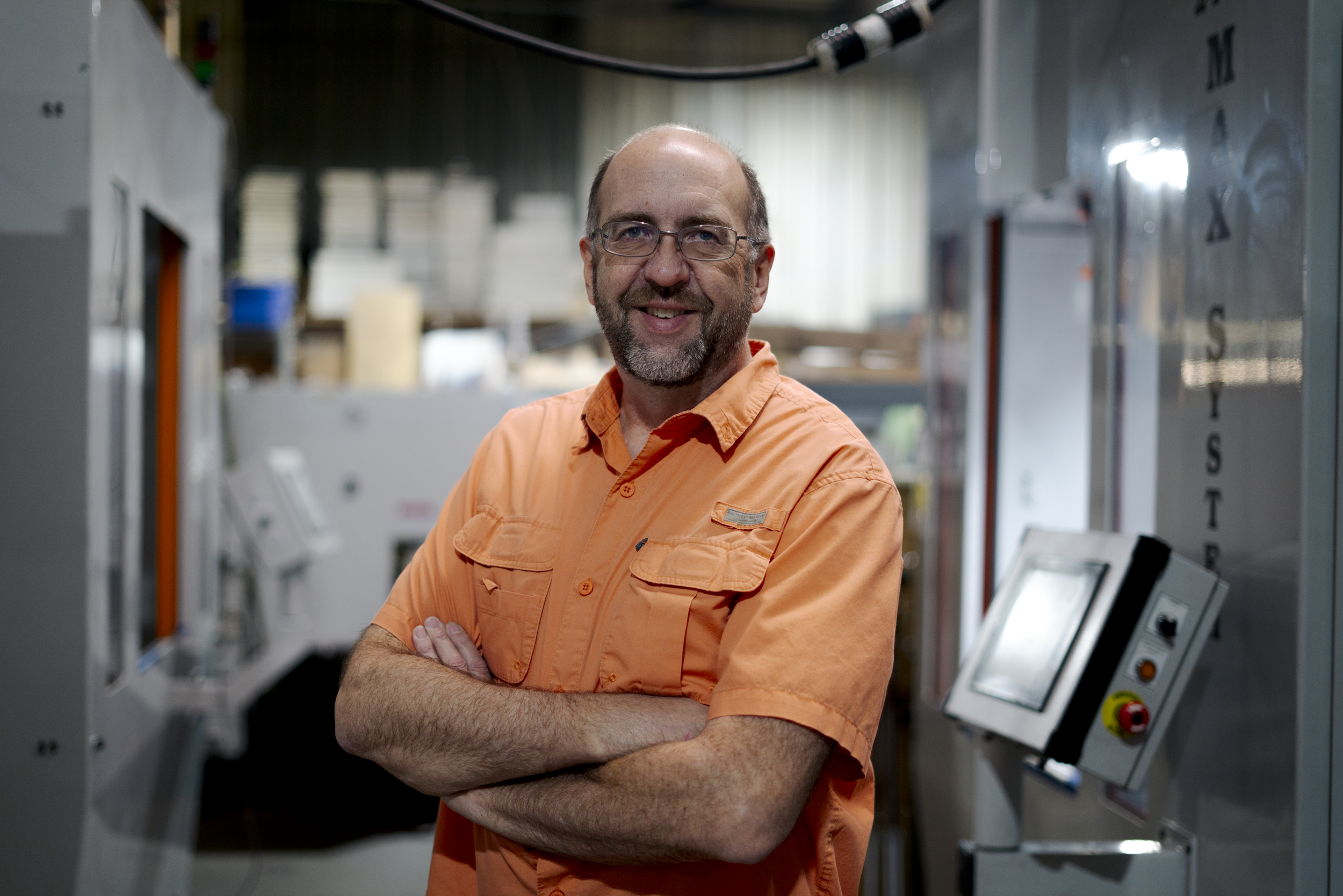
Jim Richards, founder of James Engineering, explains the top three part finishing challenges and the secret to overcoming them.
The process of finishing parts and gears before assembly comes with a set of its own unique issues. This manufacturing process is vital and cannot be skipped, or else assemblies would fail due to poorly prepared parts/gears. Finding simple, efficient solutions to these issues is crucial, as it ensures overall effectiveness and quality of an assembly.
We interviewed Jim Richards, the founder of James Engineering, and asked him what he finds to be the top three part finishing challenges. Richards has been at the forefront of the deburring industry for a little over forty years and is seasoned when it comes to overcoming a challenge.
1. Conflict with Customer Prints
“One of the biggest challenges is meeting customer requirements within blueprints,” Richards says. “Sometimes, the people writing these specifications don’t understand the tooling that is required with deburring or how it works.” Richards later goes on to say that this particular issue is not only the hardest one to solve, but the most common one faced within the deburring industry. The process of deburring is very complex, and if blueprints aren’t drawn correctly, deburring can seem impossible on that specific part because of the ultimate limitations that come with the process. “Sometimes we don’t have the kind of tools to do what the blueprints ask of us,” explains Richards, “but we’ve learned to solve these problems over the years.”
What Richards has learned is that collaboration and adaptability are key when it comes to sidestepping this conflict. The engineers at James Engineering are in constant contact with their customers in order to meet their requirements in achievable ways. “Sometimes we get companies who send in drawings that we absolutely cannot change,” Richards adds, “Take Pratt & Whitney for example. That’s a big company that requires consistency, we can’t just up and change what they’ve sent us. So we have to do what they’re wanting us to do. But we’ve learned to do the job.”
2. Cost of Consumables
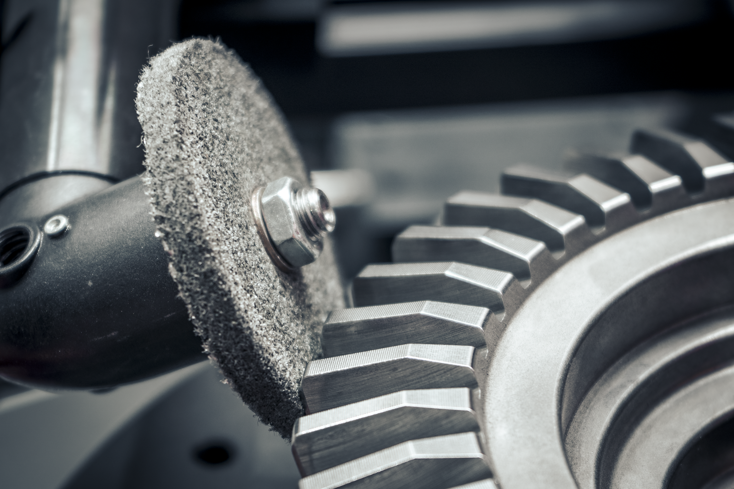
“Understandably, you can’t build a quality part with cheap materials,” Richards starts, “Sometimes you have to spend a little more to get a better part.” Richards explains that every James Engineering machine is built with the intention of using particular brands or items. If these specifications aren’t followed, the final quality cannot match what is promised by one of their machines. “The quality of chamfer we need and produce is from running a finer grit grinding wheel,” Richards explains when asked for an example. “The wheels we use are made of cotton, which don’t last as long as these tiger claw, aluminum oxide coarse wheels. Well, these coarse wheels remove metal fairly easily, but they leave a really jagged finish. People run these wheels for economic reasons, because yes, they’re cheaper, but they will destroy a part.”
James Engineering machines are known for producing beautifully precise and consistent chamfers. This is greatly due to the kind of grinding wheels they use, which are comprised of cotton and resin. The idea of using cotton in a grinding wheel is surprising to many, but in terms of chamfering, this kind of wheel is a champion of it. The cotton acts as a dampener, meaning these wheels’ tendency to bounce is extremely low, especially compared to woven fiberglass wheels. While the cost of running these coarse fiberglass wheels is smaller up front, it will actually cost a greater amount in the long run due to a high rate of scrapped parts. This is a great example as to why using the intended tools is extremely important for overall production. “We have to establish what we’re going to use and that has to be followed.”
3. Consistency of Parts Presented

The third most frequent challenge Richards has seen is the consistency of parts presented. “We often get sample parts from customers, and their conditions will sometimes change. So then we have to take samples of burrs and look at their size and decide what we can and cannot do. I’ve seen samples come in with burrs an inch and a half tall!” Essentially, machines are manufactured to handle a consistent, established size of burrs for specific parts. For example, a company will send in a dozen samples of the same part. Eleven out of twelve of these parts have burrs roughly the same size, but the twelfth will have a burr substantially larger than the rest. This twelfth part wouldn’t receive complete deburring using the same specs as the other eleven parts—it would require an entirely different set of measurements, tooling, and time. But this issue is easily avoidable as long as customers take care of one particular aspect: changing the part cutter on their CNC machines.
“When you’re making a gear or part, the hob cutter will start off as razor sharp, but it eventually wears out, naturally. We [at James Engineering] have to make sure we qualify when you change your cutter. Operators can’t be running their cutters down to total wear then give us huge burrs. So we need to establish the point of which they change their cutter so we receive parts that we’re capable of deburring.”
This may sound laborious and costly, but again, this ultimately saves money in the long run. If cutters are changed regularly, the predictability and consistency of their parts becomes manageable. This then makes it easier for James Engineering to manufacture machines that work perfectly for a shop’s needs. If the cutter is not changed frequently, extra tools must be added to a shop’s machine, costing them more in money and processing time. “You’re better off to change the cutter and leave our process simpler,” Richards explains.
So, how avoidable are these challenges?
“These are all very easily avoidable!” says Richards. “With consistency of parts presented, we just need to qualify the part that we’re going to deburr and establish that in writing. With the cost of consumables, we have to establish exactly what we’re using and write it into the warranty. Conflict with customer prints is always trickier, as we sometimes can’t change anything about the blueprints we’re sent. [We just] have to be adaptable.”
James Engineering prides itself on being a thorough and precise business—these values can be found at the core of the company. They are what make their machines so consistent and products so repeatable. There’s a reason why their deburring systems are at the top of the market.
What are the ultimate solutions?
With each customer comes a new challenge, but conflict with customer prints, the cost of consumables, and consistency of parts presented are usually given. However, after decades of dealing with the same issues, Richards and those at James Engineering have found that the following are the top solutions:
· Adaptability
· Reliability
· Flexibility
· Thoroughness
· Consistency
· Communication
By adhering to these six simple values, no challenge is too much for James Engineering.
To learn more about their machines, click here.
To send any sales inquiries or further questions, email Sales@James-Engineering.com
Types of Deburring
Let’s dive in to eight different methods of deburring!
Punch Deburring
Since its perfection in 1770, sheet metal has become a commonly used material within the manufacturing world. One of the most popular ways of cutting and manipulating sheet metal is a method called “punching”. A punch machine uses interchangeable tools to cut out shapes from the sheet metal, and it’s vital that these tools are sharp. If they aren’t, they require more force to cut through the metal, which can lead to the formation of burrs. Punch machines can deburr the pieces of sheet metal they just cut, and they do so with another set of interchangeable tools, which are meant for deburring. This method of deburring works well for pieces cut from sheet metal, but it’s extremely limited when it comes to parts with complex geometries.
Tumbling Deburring

This method involves parts/gears being tumbled in a barrel full of water and loose materials (known as tumbling media), such as glass beads, steel, or plastic. The force of the material and parts tumbling against each other will break off any present burrs and smooth out a part’s surface. Operators must be able to choose their media correctly, as some will do extreme damage to gears/parts made of other certain materials. For instance, steel parts must be paired with steel material. Tumbling is a good option for larger parts/gears, as it is a quicker way to remove their burrs compared to doing it by hand, and they are less likely to suffer overall structural damage from it. However, that risk is still there, and it can ultimately do more harm than good.
Vibratory Deburring
Vibratory deburring is like the tumbling method in the sense that parts are put into a barrel with tumbling media, but it’s more effective and gentler than its cousin method. When the loose material is vibrated against parts/gears, the force shears off burrs and other imperfections with equal force, making it a safe method for smaller, more delicate parts. This process is used frequently within industries such as the aerospace or medical industries and can even be used for parts made of wood or plastic.
Cryogenic Deburring
The cryogenic deburring method is similar to freezing off a wart. Parts are put into low-temperature chambers, where burrs are then frozen until brittle. The burrs will then get knocked off part surfaces when non-abrasive media is thrown into the chamber. This process doesn’t leave residue and preserves the surfaces of parts of any size. It’s a good option for processing large amounts of parts/gears at once, but it still lacks the precision that is necessary for complex parts.
Hand Deburring

This might be the most common—and the most time consuming—deburring method out there. Workers use handheld tools to manually complete processes such as brushing, edging, chamfering, polishing, and of course deburring. While this method allows for focused precision, workers are limited to working on one part at a time, making it extremely inefficient for high or medium volume shops. These workers also require adequate training and experience, seeing as one mistake can scrap an entire part; a little too much material taken off a part/gear can cause it to not fit into its greater assembly properly and affect its long-term efficiency. Another issue with hand deburring is that consistent chamfers are hard to achieve with it, and chamfers of poor quality will also affect the function of a larger assembly. Some manufacturers still prefer hand deburring to other methods, but it costs too much time and money to be used widely.
Electrochemical Deburring
Electrochemical deburring is a unique method of deburring that shoots currents of voltage between a cathode and a burr, ultimately dissolving said burr. This process can remove any sort of excess unwanted surface material. It’s important to maintain a gap between the cathode and part needing deburring, as this gap (paired with an electrolyte solution) allow for the transfer of voltage. It’s much more precise compared to methods such as punch deburring or tumbling deburring, and allows holes, cross holes, and intersections to be deburred easily. However, this method is limited to a small variety of materials seeing as some don’t contain the required levels of conductivity.
Thermal Deburring
The thermal deburring technique is carried out by placing parts in a pressurized chamber and setting off a series of controlled combustions, which essentially melt off any burrs or surface imperfections. The overall structure of the part/gear in the chamber isn’t harmed due to how momentary these mini explosions are, however the risk of excessive heat damage is still present. Once the burrs are removed, the part/gear is left with a thin film coating its surface and it must be cleared off before it is further processed. While efficient when it comes to removing multiple burrs/surface imperfections at once, it also lacks the necessary precision required by some industries, such as the aerospace industry.
Machine Deburring
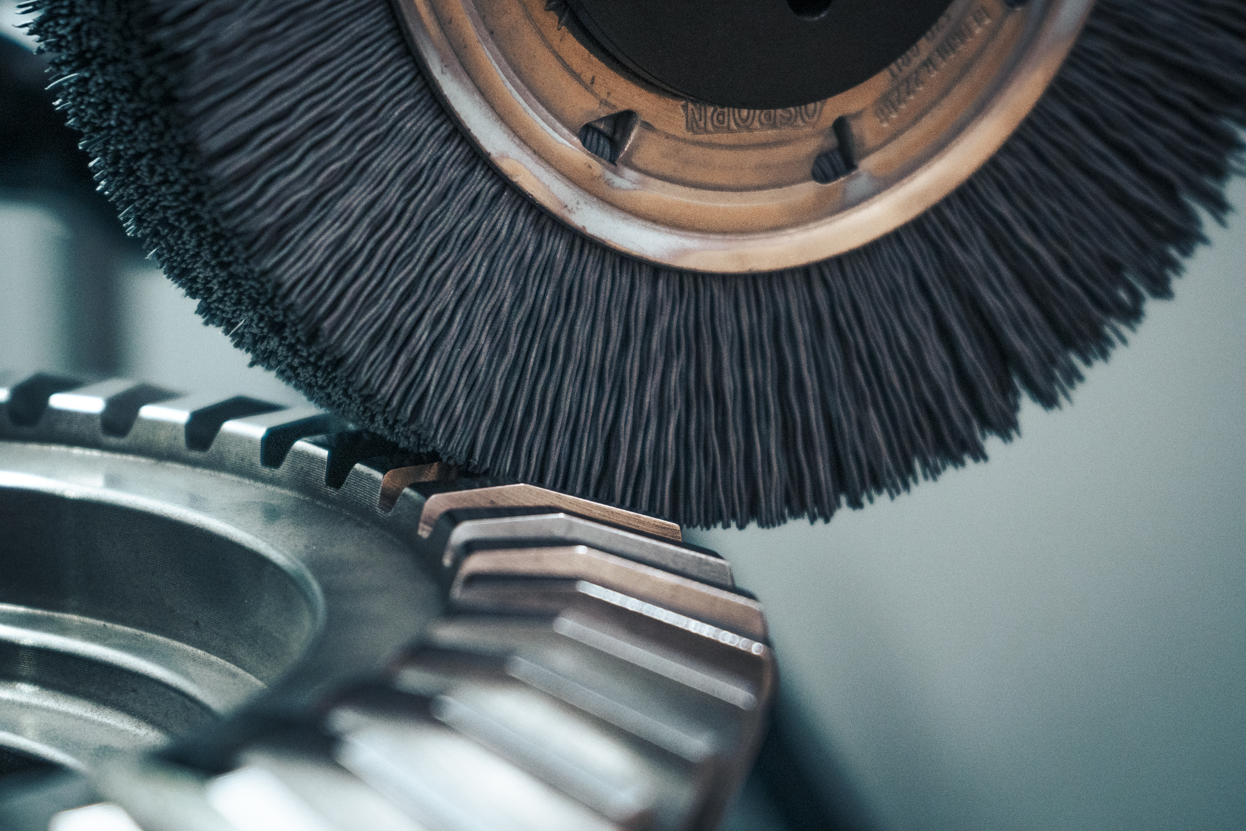
Machine deburring is the most effective method of deburring when it comes to timeliness, cost efficiency, and precision, and has been gaining popularity as the demand for all three of these factors has grown dramatically over the course of the last few years. Machine deburring extends to both CNC machines and finishing machines, such as the MAX System from James Engineering, a high precision deburring and chamfering machine. CNC machines are most efficient when it comes to cutting parts, but they also have limited deburring capabilities. The MAX System and its one-of-a-kind technologies allows the machine to deburr and chamfer, radius, wash, and brush a part concurrently. This is due to its multi-tooling feature, which is customizable to any company’s needs. It also features an 11-axis overhead gantry system, making any angle reachable. The MAX is a great option for both parts and gears of any size and any complexity, and with Focused Deburring (a technology unique to James Engineering), burrs can be targeted—something only James Engineering finishing systems are capable of.
Which one is right for you?
These eight methods of deburring are used for a wide range of industries, parts, and gears, and each have their own pros and cons. Finding the right one for your company ultimately depends on the volume at which your shop is producing, and what parts/gears you produce. The lower your shop’s volume is, and the simpler your parts, methods such as hand deburring can be a reasonable choice. If your shop is producing at a high volume and working with a wide array of gears/parts of a variety of materials, a specialized finishing machine such as the MAX System is the most time and cost-effective move to make. Doing your own research is important, and you know your shop’s needs the best… but you can never go wrong with the MAX.
Innovating Tomorrow
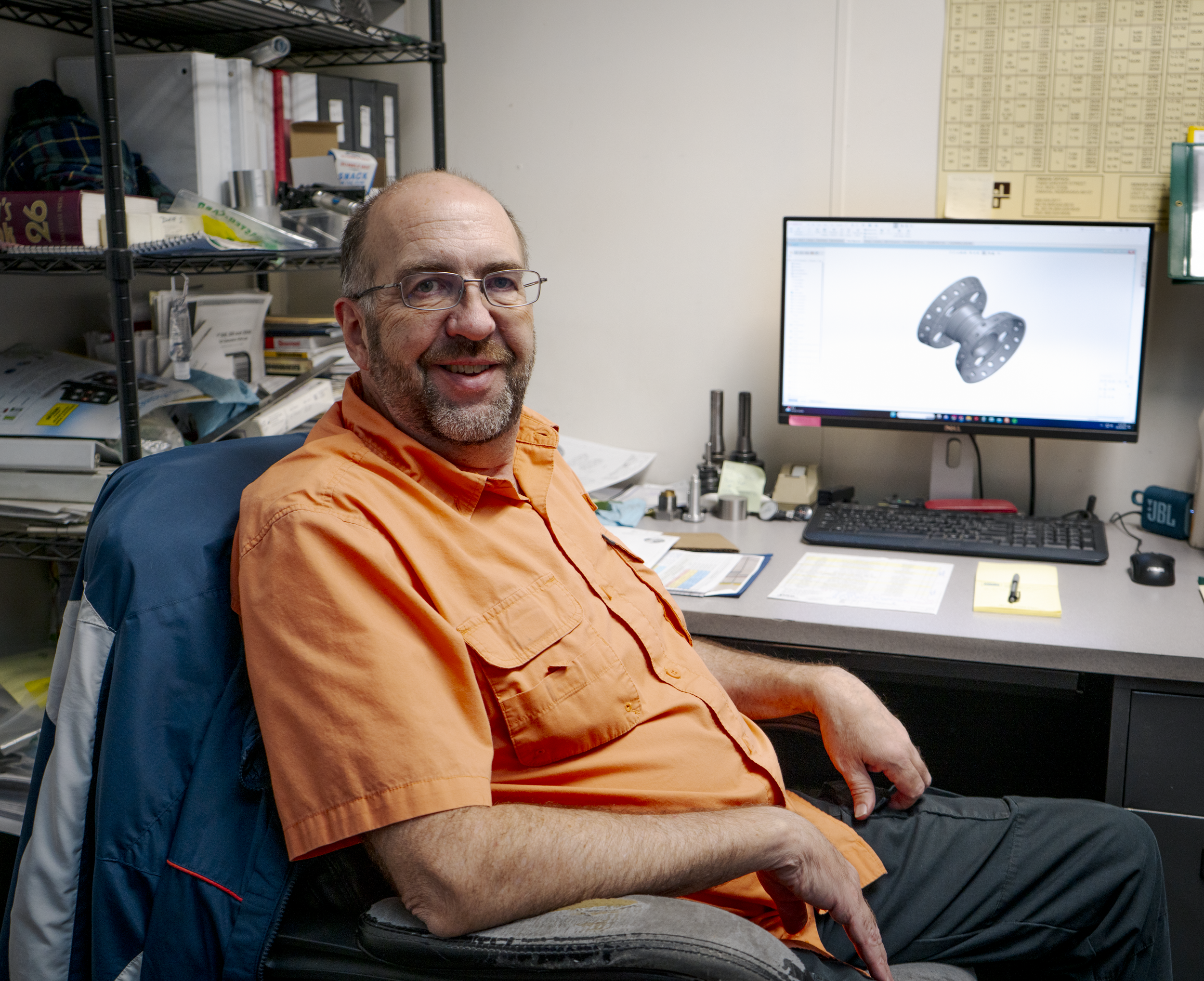
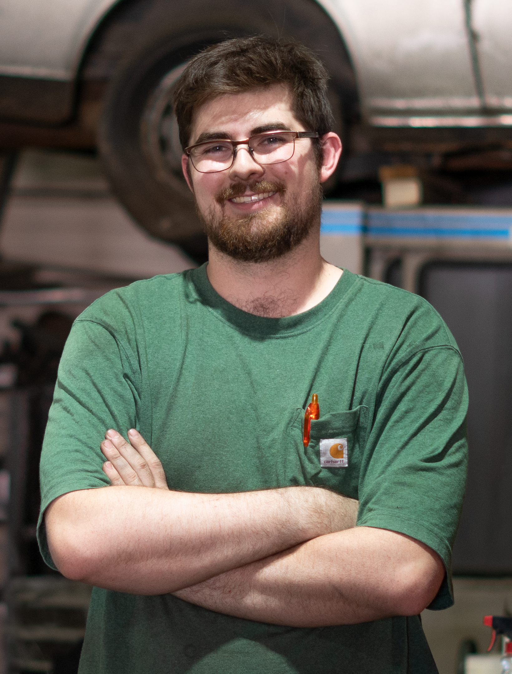
James Engineering’s own Dave Schlosser gives us a sneak peek into his career as a mechanical engineer.
Within the walls of James Engineering, a dedicated engineer works tirelessly to perfect vital components and assemblies. Dave Schlosser, head engineer for the Coloradoan OEM shop, and his crew of engineers team up to draw, assemble, and manufacture the one-of-a-kind deburring machines sold by James Engineering. But Schlosser’s career in engineering began way before he joined the J.E. family.
“I started when I was 13 in my dad’s garage; he welded, so I’d help him with welding. Then I wanted to be a machinist because my dad was one,” Schlosser states. He got his foot in the industry’s door early, which eventually nudged him to go to school for machining. Eventually, he dipped his toes into quality control before migrating into the engineering department for a different company, which was eventually bought out.
After years of completing personal projects, such as an adapter plate for his Volkswagen transmission, Schlosser realized not only was he a talented engineer, but a creator at heart. So when he found his job at James Engineering, he knew it would be the perfect position to nurture his creative desires. Schlosser gives a little insight as to what his daily tasks consist of:
“I lead the engineering team. We got a couple of interns and full-time guys. I’ll also run what goes through the machine shop and help prioritize [the projects].” When asked how the position keeps his creativity flowing, he explains, “We do drawing revisions, part revisions, and new product development.”
Updating assemblies and part drawings is crucial—this process ensures that both the engineering department and shop floor are on the same page before pieces/assemblies are completed. Concise drawings create clear communication between the two groups, which ultimately does three things: decreases the number of errors made in production, increases shop efficiency, and allows for the creation of new products. Schlosser is central to this procedure. “We started making our own cogged pulleys,” Schlosser explains, “Belt pulleys, not like gears. [These] pulleys have slots in them for grooved belts. It’s like a timing belt in a car, which has little cogs in them. This eliminates backlash in our machines. We just started doing these about six months ago.”
While this process gives Schlosser the outlet he’s always wanted, it has proven to be the biggest test for him during his time at James Engineering. “Because we are a small company, there’s a lot of tribal knowledge of how things work. It’s not quantified in a lot of cases in drawings, so that’s a big challenge—getting that knowledge from somebody’s head and getting it put [on paper].”
Despite its trials, this shared knowledge is one of the most unique parts about working at James Engineering. “There’s tech here that you don’t see anywhere else. And Jim’s got [decades] of knowledge, so I learn from him every day.” Jim Richards is the founder of the company and works closely with the engineers every day. “I take what I know and keep adding on to that.”
Schlosser has collected new information and experience throughout his whole career. The mechanical engineering industry has only continued to evolve, introducing new technology and methods to its workers at astounding rates. “When I first got into the industry, CNC machines were brand new. Now, everything is computer controlled instead of being done by hand,” Schlosser reflects. With CNC machining giving manufacturers the upper hand in efficient and speedy production, engineers such as Schlosser can turn all their ideas into reality. ‘There’s a lot of stuff I want to develop with the tech here. Jim and I talked about building a table with our gantry system where you can plug in a router and a laser. This would be used instead of having multiple machines that do the same thing. I also want to do a whole series of our own products that don’t even necessarily have to do with deburring.”
With new waves of engineers pouring into the industry every year, mechanical engineering will further evolve. Schlosser offers them his seasoned advice: “If you’re going to be a mechanical engineering designing mechanical parts, learn machining! You don’t have to be an expert at it, just know how to make parts because then you can make drawings a lot faster. Go get a job at a machine shop just so you can learn how materials are cut. With experience like that, you’ll be years ahead of your peers who also just got out of school.” As somebody who worked in a machine shop before entering the engineering field, Schlosser knows firsthand how effective this method can be. “Learn how whatever you’re working on is made, whether it’s plastic, metals, etc.”
The mechanical engineering field is one that provides countless learning opportunities, and Schlosser cannot stress enough how important it is to take each one you can get your hands on. By doing so himself, he has worked a plethora of jobs that have built upon his knowledge every day. Schlosser’s time at James Engineering has not only taught him about hydraulics and pneumatics, but it has strengthened his abilities to problem solve and lead a team. Schlosser is coming up on his third year at the shop, and is given the freedom to do what he loves best—create.
“It all comes from your head, and then it’s in your hands. That’s what’s really cool about mechanical engineering.”
A cool career, indeed.

FIGHT! Robot vs Gantry System
The presence of robots increases every day within the manufacturing industry, but James Engineering has managed to manufacture without traditional robots from the start—and here’s how.
Robots have been slowly integrated into the manufacturing industry since “Bill” Griffith P. Taylor invented the first industrial robot in 1937. As the industry grew, so did the abilities of robots, which really took off in 1981 when the first robot with joint-mounted motors was created by Takeo Kanade. This later lead to the invention of intelligent robots in 1992 by FANUC (who is now a leading robot manufacturer). Nowadays, you could walk into any large manufacturing/industrial factory and be greeted by an army of robots whirring away, day and night.
There are several tasks that robots are able to perform, including painting, material handling, material removal, assembly, and even welding. These tasks are described as “repetitive applications”, as robots can be programmed to complete these kinds of tasks quickly and efficiently. So where a human would become fatigued after such repetitive work, the robot won’t falter in its workflow. Collaborative robots (also known as “cobots”) work together with humans to complete applications in a conducive manner by finishing monotonous tasks, allowing the human employees to focus on more intricate and precise jobs. This sounds perfect on paper, but robots still require a lot of training to operate.
After founding James Engineering in 1980, James Richards set out to create and manufacture his own robot. The company was working on the initial creation of their MAX System, an all-encompassing finishing machine, when Richards tried his hand at robot design, but he quickly came to realize just how limiting robots can be when it comes to efficient manufacturing.
“What I found is that robotic arms have a very limited workspace envelope,” says Richards. “For manufacturers, that dead space becomes an issue when workspace is premium.” Due to the typical internal setup of robot arms and their limited stroke, they are unable to reach the corners of their workspace, ultimately leaving behind a lot of precious unused space. “Another problem with them however is that eventually the arm is going to bend and lower when enough weight is added to it,” he continues, “It’s like if I took a broomstick and extended it off a table and put weight on the extended end—it’s going to bend and dip. It’s the same even with steel arms.” This bending then creates vibrations (also called chatter) that leave waves on machined surfaces. Chatter will greatly reduce both a product’s quality and productivity. The bending of robotic arms also decreases the robot’s efficiency over time and exterminates any precision it might have had previously. “[A robot] was initially designed to be a pick-and-place unit without much precision.”

Since James Engineering focuses on manufacturing and selling high end deburring and chamfering machines, the loss of precision would make our machines worthless, hence why Richards scrapped his designs for a “traditional” robot. He eventually built a different kind of robot known as a gantry, which is “a frame structure raised on side supports so as to span over or around something” (Merriam-Webster.com, Oct 2023). The gantries used in James Engineering’s machines use straddle mounts and feature a moving truck running between each end of the mount. Because support is coming from each side, any pesky bending motion is removed, resulting in a longer-lasting mechanism. The biggest advantage to using a gantry system is it can accomplish all the movement a robot is capable of (and more) using only 3 axes instead of a robot’s 4. “My machines will go back and forth for years without losing any accuracy because they’re supported from both ends,” Richards explains.
“With a robot, there’s also a limitation of stroke if a part is too big to put on a rotary table,” he continues. A design flaw commonly seen amongst robots is where the actual arm itself is placed—directly in the middle of the machine. This eats away even more precious space, but with the James Engineering overhead gantry system, the “arms” of the machine can be retracted above the workspace. Now, the gantry system is not necessarily something that is unique to James Engineering; lots of other companies utilize gantry systems and even make universal erector sets of them. “[These sets] are like building blocks,” Richards says, “Gantry systems are like modules. You can build one axis that goes back and forth and you can buy multiple of those. You do have to buy all of the components though to make them do what you want.”
But Richards didn’t build your average gantry system—he built one with the future in mind. Currently, the gantry system within the MAX is capable of deburring, chamfering, surfacing, washing, and brushing parts/gears. But the ultimate goal of the MAX is to make it capable of accomplishing 14 applications in total. “I designed the MAX to one day be able to paint parts, [use] sand blasting, [carry out] rudimentary machining, assemble, 3D print with both metal and plastic,” Richards reveals. “We could even make [some] machines capable of this now. But the MAX was built with look-ahead capability.”
James Engineering has used the gantry system for decades now, and it has yet to fail against a typical robot. Due to its unlimited movement and reinforced framework, Richards states that, “A robot has no advantage over us.” All the MAX Systems offered by James Engineering include the gantry system, further proving their overall precision and reliability.
“Everybody is trying to use robots in ways they weren’t designed for: polishing, machining, assembly, welding. Because of how these robot arms are built, they start to lose accuracy within 3 to 4 months,” Richards describes, “But for a CNC/deburring machine, we need accuracy twenty times better than what a robot can do at best.”
And that’s exactly what the gantry provides.
Interested in testing out the wicked capabilities of the James Engineering gantry system? Send any questions or inquiries to Sales@James-Engineering.com and we’ll get back to you ASAP.
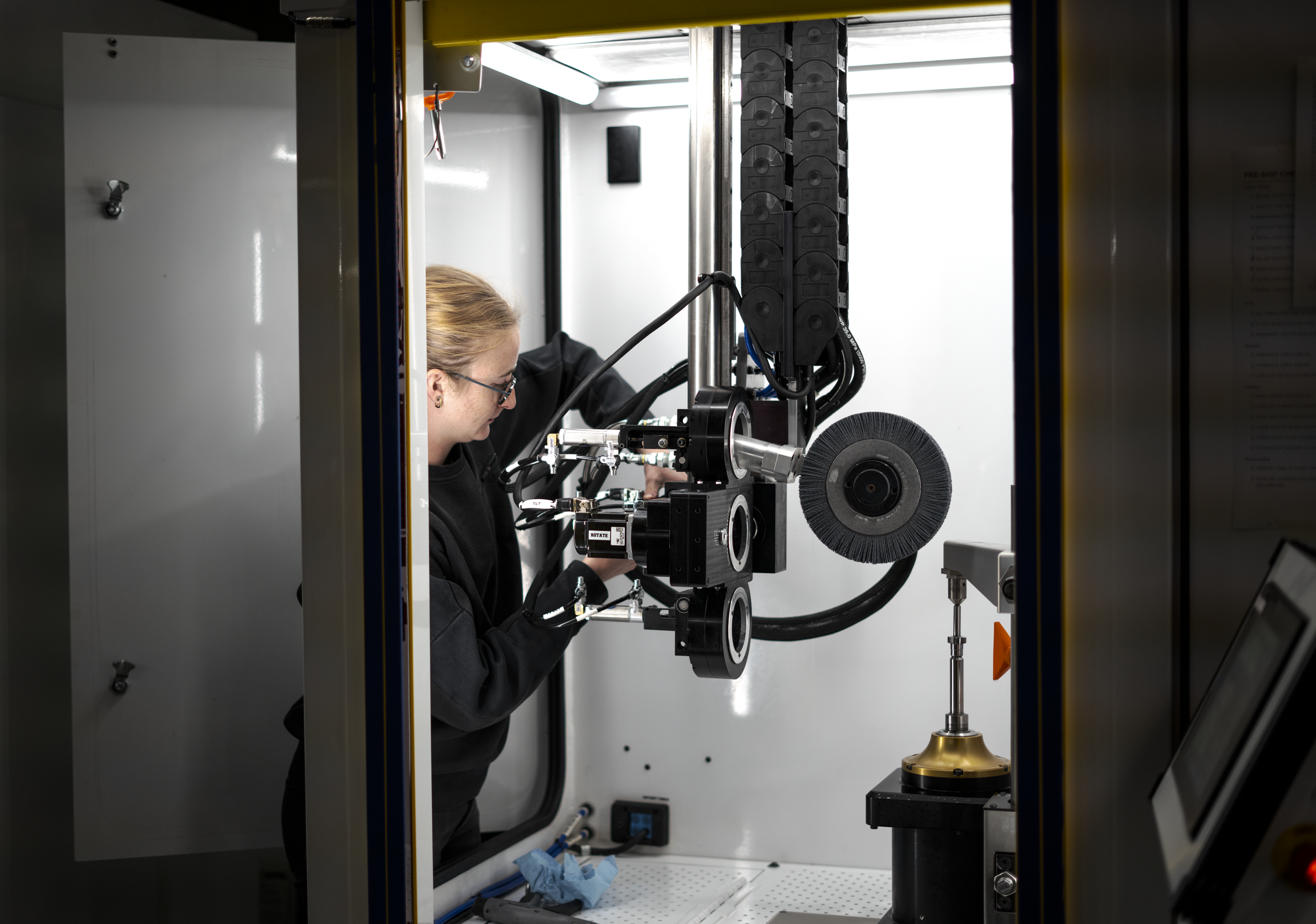
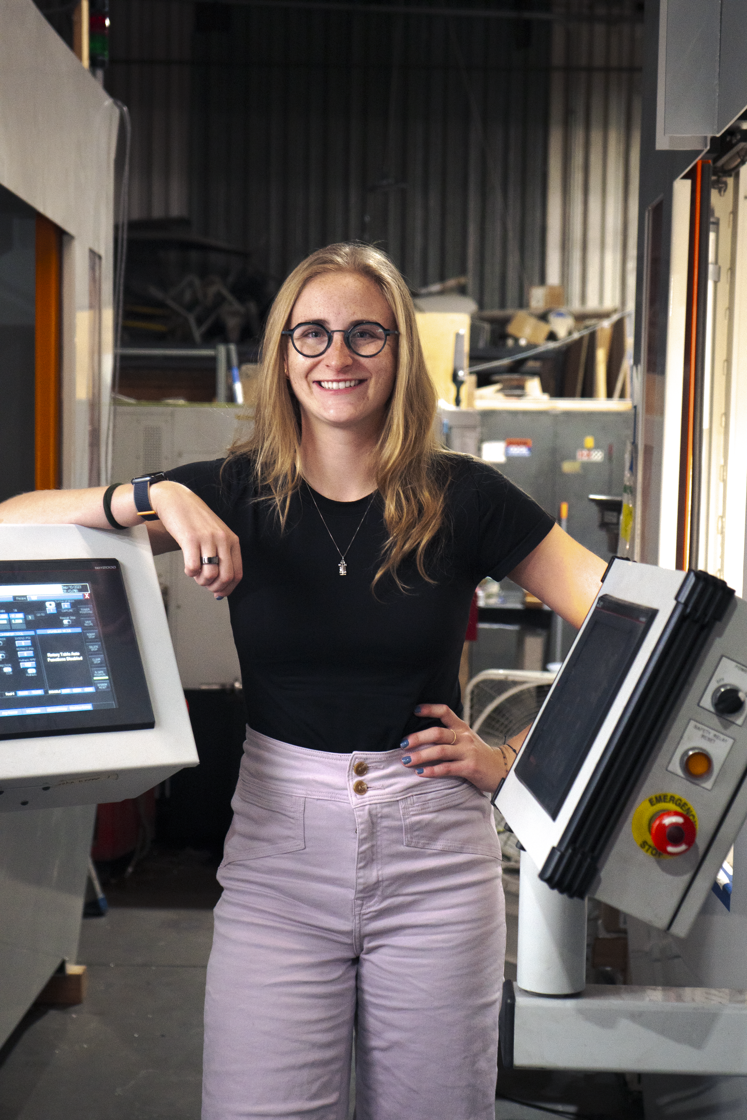
The A1 Intern
Quinn Gossett explains what she’s learned during her time at James Engineering and how it has prepared her for her future in mechanical engineering.
Fluttering between the stone halls of CU Boulder and the bustling shop of James Engineering, Quinn Gossett studies hard and works even harder. Shortly after finding out about the family-owned OEM shop through a friend, Gossett began her job as a mechanical engineering intern—the perfect gig for a mechanical engineering undergrad.
“I chose to study engineering because it is the perfect combination of creative problem solving and science, two things I love,” explains Gossett. “Oftentimes there are several ways to solve a problem, and that requires truly creative thinking, which is something I’ve done naturally my whole life.” Gossett quickly slipped into her role at James Engineering, tackling any challenges presented to her with a fresh-faced eagerness. “One of the first obstacles I faced was establishing a system of organization for myself. The machines that [we] build are very complex. I was able to overcome that challenge by being thorough and asking questions as soon as they came up.”
But by pushing through and solving these challenges, Gossett gained expansive hands-on experience which wound up giving her an in-depth look at the engineering career field.
“My work [at James Engineering] stretched me outside what is traditionally considered mechanical engineering. I worked on project management, component design, and [even] hands-on assembly and manufacturing. Since James Engineering is a small company, there is ample opportunity to work in these different areas. Not having a hyper specific specialization has allowed me to develop a well-rounded set of skills.”
Gossett expanded upon her project management skills by creating systems that tracked the building process of specific machines. These systems revealed any problematic dependencies to the team of engineers, while also providing them with clues as to how to make the building process more efficient. Before building could even really start, however, Gossett had to go through the trials-and-errors of component design process. Seamless component design is crucial, which Gossett discovered, especially since she had to figure out how to incorporate new parts into already-existing assemblies. “It was necessary to explore multiple design options instead of immediately committing to one design for full development,” she writes. Once a component was correctly designed, the assembly process could begin, which allowed Gossett continuous hands-on involvement. Gossett then discovered that assembly can show intricacies that her CAD models can’t, further enhancing her knowledge when it comes to designing new parts.
"Developing skills across several disciplines changed my perspective on how the engineering process works as a whole,” Gossett continues, “Even when working on one individual component, it is critical to understand what it takes to manufacture the part.”
James Engineering constantly encourages continued learning when it comes to the engineering industry—both for the new and the experienced. Just one internship or job opportunity can completely change an engineer’s perspective of the industry and teach them something new they wouldn’t have been able to garner anywhere else. After her time at James Engineering, Gossett offers some advice to those interested in becoming mechanical engineers themselves:
“Be prepared to work hard and work creatively. There are times where you will fail, but that is part of the learning process. The mechanical engineering curriculum reaches across a wide range of disciplines and is extremely well rounded, [so] as long as you are trying your best, that will get you far.”
Mechanical engineering is a stimulating and rewarding industry that always asks the question, “How can this be better?”. As engineers design practical, efficient, and complex solutions to the multitude of problems that pop up in our everyday lives, it’s important for them to remember how their work impacts the world around them. “My biggest goal is to leave this world better than I found it. Through any industry I work in, I always want to use my skills to create solutions that make this world a better place for every human and every creature that calls Earth their home.”
Gossett has already succeeded at making James Engineering a better place.
To all the engineering students out there, we at James Engineering commend your dedication and inspiration—it is a rigorous industry, but it is worthwhile. If you are interested in learning more about James Engineering and how we contribute to the mechanical engineering industry, click here to check out the rest of our website. In the meantime, keep studying, keep creating, and keep innovating.

Happy Manufacturing Day!
Today is National Manufacturing Day, and the beginning of Manufacturing Month! Let’s dive in to the holiday’s history and importance.
Manufacturers! Hold your tools high, wear your grease stains with pride, and celebrate all your hard work, because today is National Manufacturing Day, and October is Manufacturing Month!
Didn’t realize that Manufacturing Day is a national holiday? It’s okay—it’s a relatively new holiday, as it was first declared on October 12, 2012. Only eleven years of celebrating an industry that has shaped America for hundreds!
The idea of Manufacturing Day was created back in 2011 in Rockford, Illinois, (but was officially recognized in 2012) as a way to break the industry’s stigma of hostile environments and labor-intensive work. The ultimate goal of the holiday is to shed light on how innovative and exciting manufacturing actually is, especially with the advanced technological skills and tools that have spurred the evolution of the industry, such as robots, computers, CNC machines, and more.

The manufacturing industry is one of the leading 10 industries in the United States, supplying 8.41% of the national workforce with jobs all over the country; that means roughly 12.5 million people work as or for manufacturers every year.
In 2021, 149,000 people worked for manufacturing companies in Colorado alone, making up 5.36% of the state’s workforce. Yet even though the industry is one of the tops in America, the growing shortage of trained workers has begun to affect the industry, leaving big gaps of unfilled positions.
These gaps then increase production time, lower company efficiency, and stunt industry advancement, which is why the breaking of stigmas and installment of internships and in-house training programs have become so crucial for recruiting the new generation of workers.
Here at James Engineering, we highly value learning opportunities and internship programs. Teaching the younger generation of manufacturing engineers about the industry advancements has been crucial for setting the stage for our future as a company, as well as their futures as individuals in the workforce. We provide our employees and interns with as much hands-on experience as possible, and we work together as a team to navigate the ever-changing world of manufacturing engineering. In Colorado, the top growing sect of the manufacturing industry is aerospace product and parts, which is what James Engineering, a Colorado-based company, has specialized in since being founded in 1980. We have become experts when it comes to aerospace part finishing, so much so that every plane in the sky has been touched by one of our machines. We know what it takes to succeed in the manufacturing industry, and we pass on our knowledge to those who are dedicated to further advancing our innovations.


Today it’s important to reflect on the impact the manufacturing industry has had on not only America, but the entirety of our world. The ever-developing industry has supplied millions of jobs to millions of people, and without these people, our planet would be a completely different place. Cars, airplanes, cellphones, medical equipment, even the clothes in your closet would cease to exist without manufacturing and all its astounding accomplishments. Here at James Engineering, we highly encourage those interested in the manufacturing industry to take any opportunity to learn more about its how’s and why’s, and to not be afraid to contribute their own original propositions. Manufacturing is no longer a dark-roomed, physically grueling industry that’s vicious on the body and mind—manufacturing is a technological, innovative industry nurtured by bright minds, inspiration, and passion.
For the rest of October, take a moment each day to observe the objects, equipment, and machinery around you that have been made possible by our world’s manufacturers. Take any chance you get to learn more about our mechanical surroundings, and push yourself to share your ideas with the world. You never know—you may be the next person to evolve the industry.


If you’d like to know more about the James Engineering impact, check out the rest of our website at https://www.james-engineering.com/. If you’re interested in joining our team, please send your resume or inquiries to Employment@James-Engineering.com, and we’ll get back to you as soon as possible!

Under (Air) Pressure
The air we breathe and the power it creates—how air motors work and why they’re preferred.
Air motors (or pneumatic motors) have been used in the manufacturing, industrial, and tooling industries for hundreds of years, of course evolving as the industries have changed. Nowadays, air motors can be sorted into three kinds: piston, rotary vane, and turbine. Here’s a breakdown of each type and how they work:
1. Piston motors utilize series of pistons that force feed compacted air down into a chamber, which is held open by a spring. When this air gets pushed deeper and deeper into the chamber, the spring is forced to bend. Once it has moved through the entire length of the chamber, the spring resets, and voila—rotary mechanical energy is created. These motors tend to move slower than the other two kinds, but they’re highly reliable, and are frequently found in hydraulic systems.
2. Vane motors are powered by a group of vanes that force chambers to expand open as they spin. As compacted air is pushed up against these moving vanes, it forces the motor to spin, which in turn creates the rotary energy. These motors can work quickly depending on what size they are, however they are known for working faster than piston motors. Vane motors are typically seen in natural gas engines, as the natural gas (as opposed to regular compressed air) is what applies the pressure against the vanes to make them move.
3. Turbine motors are small yet mighty, powered by air extension and velocity to create rotary energy (very similar to a turbine engine, which is where wind-generated energy comes from). These motors can be found in a lot of hand-held tools; even though they are small, they can spin at speeds up to 180,000 rpm and don’t add almost any extra weight to the tool.

What’s the benefit of using air motors?
There are a couple scenarios where air motors are preferable over electric motors.
For one, air motors don’t emit extra heat, which means they can work at a wide range of speeds without overheating. Air motors are much cheaper to replace than electric motors, and electric motors will overheat, resulting in a high-cost repair.
This also makes them safe to use in volatile settings. Since they don’t overheat, they won’t throw off any excess sparks that could possibly ignite any explosive vapors or particles.
Air motors are reversible. You might be thinking, but so are electric motors! You’re not wrong, but electric motors generate high levels of extra heat when reversed, and reversal will put unnecessary strain/shock on the equipment it’s running. Since air is compressible, it prevents all that extra strain and prevents any possibility of shock ruining equipment or disrupting load. So if air is suddenly reversed in an application, the air motor will simply reverse itself back.
Air motors are also compact when need be. Their tendency to be light weight also contributes to their lack of emitted heat, therefore making them even safer in explosive conditions.
James Engineering Air Motors
Here at James Engineering, we manufacture and sell a variety of air motors to fit needs of all different sizes and requirements. We offer both disposable and repairable motors at competitive prices that can be used in machining centers, robots, cobots, custom machinery, automation, and more.
Our air motors are precision machined at 1.75” diameter mounting surfaces, making them ideal for applications that rely on precise location and repeatability.

If you’d like to learn more about our air motors, please check out our air motors page; there you will find the specifications of each kind we offer.
If you are interested in purchasing one of our air motors, please reach out to Sales@James-Engineering.com, and we’ll work together to send you the perfect air motor for your operation.
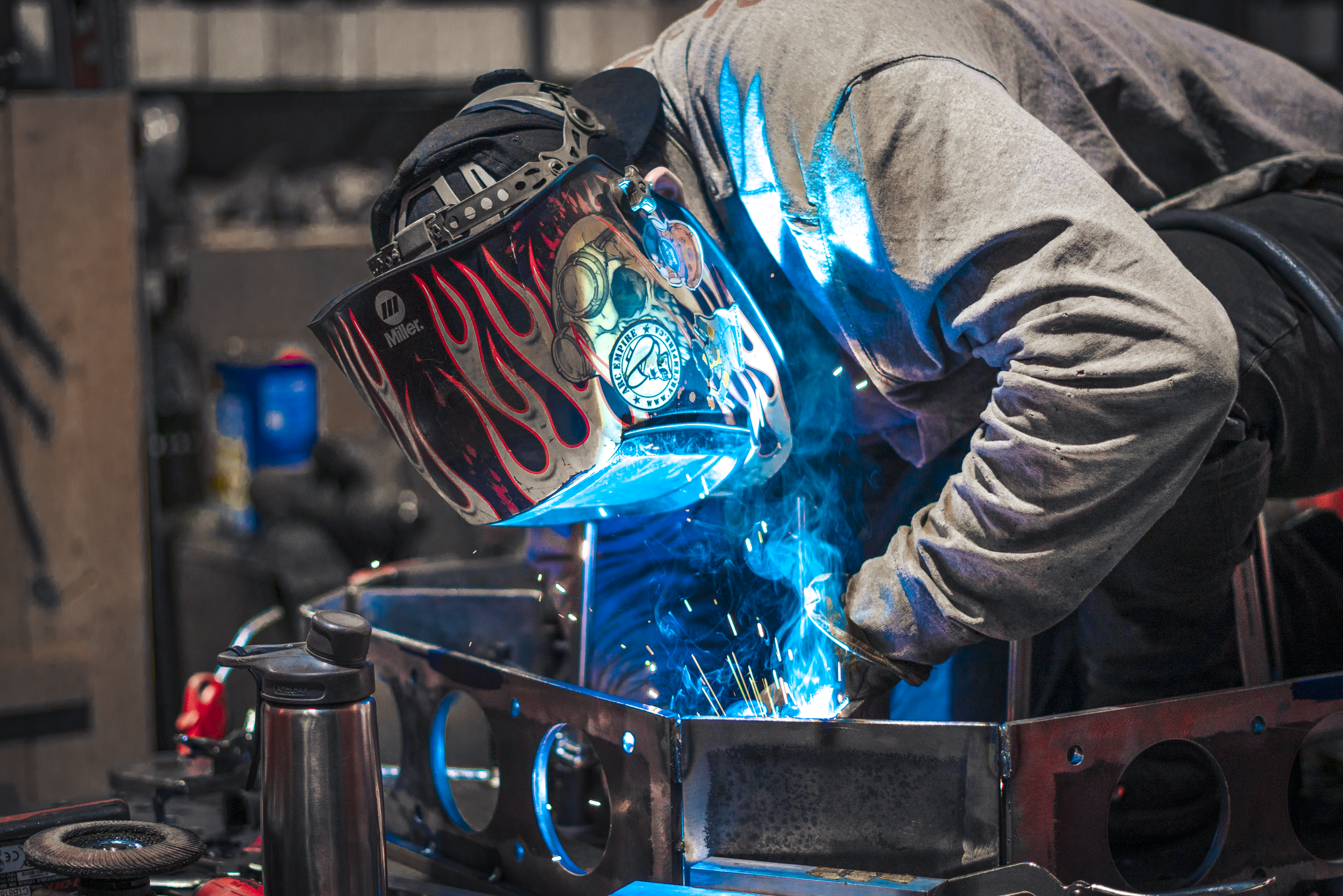
The Torchbearer
A spotlight on Masenn Lewis and his welding journey.
Bent over a worktable and concealed behind a scratched hood decorated in flames, Masenn Lewis, lead welder at James Engineering, is laser-focused on the project at hand: welding components for a cement 3D printer.
Lewis has been a welder at James Engineering since March of 2022. Prior to finding his place at the family-owned deburring and chamfering machine shop located in Broomfield, Colorado, Lewis had eight years of welding experience, working on anything from firetrucks to underwater pipelines. He attended the Divers Institute of Technology located in Seattle, where his underwater welding journey began once he’d earned his certificate. “[As an underwater welder] I’ve been all over the place. I was in Dutch Harbor, Alaska for almost a year, working with crab fishermen doing underwater construction. My favorite place was at a dam job in Austin, Texas.” Underwater welding is argued to be the most dangerous career in the country, with a fatality rate of 15%. After sustaining major injuries during his time as an underwater welder, Lewis moved from Texas to Colorado to look for something a bit drier.
Masenn lewis
“I was up in [Colorado] doing a handful of interviews,” he recalls, “and [James Engineering] offered to hire me on the spot.”
His skills did not go unnoticed, and James Engineering just knew they had to have him on their team.
But just as Lewis has played a vital role at James Engineering, they have played a major part in Lewis’s professional life. “I’ve worked for other companies where you don’t have access to the engineers to figure out what problems are happening, [but here] I’m able to talk to the engineers whenever I need to,” he says. “It’s a strong suit of the company.” Without collaboration, the manufacturing industry as a whole would fail. James Engineering highly values teamwork, and Lewis has experienced firsthand just how valuable a strong team can be. “People here get along really well, and it makes it easier to work for sure.”
This collaboration then provides endless learning opportunities, especially in the face of hard challenges. “We’ve had to work on parts of the enclosures where it’s impossible to do what we need to do,” Lewis answers when asked what challenges he’s had to overcome during his time at James Engineering. “Jim, Scott, the engineers and I figure out different ways to get things done.”

Tips from the torchbearer
In an industry that requires so much precision, Lewis offers up a few helpful tips to those who are looking to try their hand at welding.
“Don’t be afraid to get your hands dirty. Welding is an industry where you have to work hard, there’s no reason for you to watch people work and just sit around… Always have an open mind when it comes to welding. There’s a thousand ways to do something. One time it might work and the next time it might not, so you have to keep an open mind working on stuff.”
Lewis’s mastery of welding can be seen throughout every project he’s a part of. His dedication and craftsmanship reflect the steadfast values James Engineering upholds, and it’s employees like Masenn Lewis that strengthen our very foundation as a company.

No-Slip Grip
James Engineering Manufactures and sells grippers with unorthodox technology, reducing slippage and promoting efficiency.
What is a gripper? Well, just think about its name! Grippers are a device that allow robot arms to grab, hold on to, and move items, and are a key component when it comes to automatic assembly. Without them, parts couldn’t automatically be loaded in/out of machines, which is something that ultimately saves businesses a lot of money and time. For companies that process a high volume of items every day, an automatic machine is ideal; by the end of the year, an automatic machine will cost said company half of what it would’ve taken to hire an operator. These machines are essential for some businesses, but without grippers, they wouldn’t be able to function.
Grippers have a pretty simple function, but their structures and abilities can vary. Here at James Engineering, we manufacture and sell three main times of grippers: your standard gripper, a failsafe gripper, and a parallel gripper.

standard gripper
The standard gripper is one we’re all familiar with, as its arms open and close as air pressure is turned on and off.
These grippers are sturdy workhorses, but if there’s any malfunction with the air pressure, their arms will release whatever item it’s holding. This could potentially cost businesses a lot in damages, both for parts and the overall machine the gripper is inside.

failsafe gripper
James Engineering came up with the failsafe gripper as a way to combat heavy reliance on air pressure. Initially, operators will notice the failsafe gripper is powered by an air cylinder, but these grippers are actually made failsafe by internal coil springs.
These springs keep the arms of the gripper closed, even if air pressure were to fail. This ensures that neither part or machine will sustain any damage due to drops.

parallel gripper
James Engineering also manufactures a parallel gripper featuring technology unique to us. These grippers don’t swing open and closed like the aforementioned grippers, but instead slide on parallel axes. That means these grippers are perfect for picking up long, thin, or abnormally shaped items with ease. Your typical parallel gripper will have exposed tracks, making them very hard to keep dirt-free.
This contamination will ultimately wear down the gripper and create play in its arms. Play will make the arms bend, making them unable to keep hold of the items they need to grab. The difference in the James Engineering grippers is that they utilize a technology known as linear motion slides. These slides are not limited to grippers, but are a game changer when it comes to parallel gripper function. These slides allow the arms to roll on bearings, which squish dirt out of the tracks and prevent unnecessary wear. The bearings will also prevent play, so the lifetime of the James Engineering parallel grippers will outlast those of other competing grippers..
James Engineering believes in inventing the unorthodox, providing buyers with the most precise and efficient technology on the market. Not only are we deburring and chamfering machine manufacturers, we also manufacture items like grippers, as well as an array of other products. If interested in purchasing a gripper, or looking into what other products we offer, check out our PRODUCTS page.
But for now, get a grip and switch to a James Engineering gripper—we won’t let you slip!
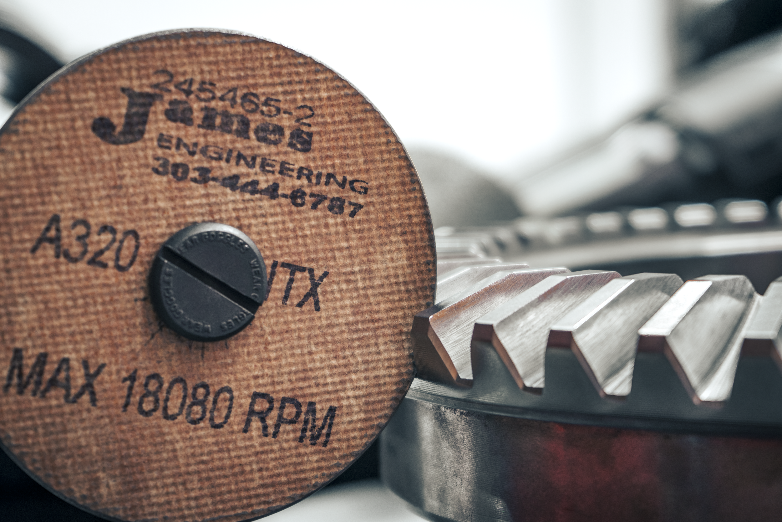
The Grind Never Stops
It matters what your grinding wheels are made of.
Grinding wheels are vital in the manufacturing world—they’re how machinists polish rough edges and achieve consistent chamfers. The size and abrasiveness of these wheels very depending on what materials they’re made of. This will directly correlate with what gears/parts the wheels are used for.
Here at James Engineering, we have an extensive stock of various grinding wheels and sell them at competitive prices. Let’s get into the 3 main wheels we sell and why you need to know the difference between them.
—

1. The Woven Fiberglass Wheel
This is your typical grinding wheel made from a homogenous blend of aluminum oxide and powdered resin. The tops and bottoms of these wheels are pressed with fiberglass, which acts as a strengthening agent and ensures the wheels don’t break while spinning.
Pros: They’re quick, and they’re aggressive, meaning their time efficient and great for cutting.
Cons: They can sometimes be a little too aggressive. These wheels can cut too deeply and have an extreme tendency to bounce, as they have no dampening factor.

2. The Woven Cloth Wheel
This wheel is comprised of cotton, liquid resin, and aluminum oxide. You might be thinking, cotton, really? But it really works! Strips of cotton cloth are layered between layers of resin, and these many layers keep the wheel’s structure from falling apart.
Pros: These wheels are great for chamfering due to the fact they don’t bounce nearly as much as fiberglass wheels do since the cotton acts as a dampening agent. The fact that they’re softer, and don’t have as much bounce, means the parts/gears they’re working on can be spun at faster rates, achieving a quicker and smoother chamfer.
Cons: They’re a bit too soft for cutting. Believe it or not, cotton isn’t very sharp.

3. The Woven Carbon Fiber Wheel
This is the most unique wheel sold at James Engineering. In fact, it’s so unique and rare that we are the only ones to carry it! These wheels are made of carbon fiber and resin, and nothing more. There’s no abrasive added to them, but the carbon itself acts as a very mild abrasive.
Pros: They’re perfect for those with very niche needs. They create extremely subtle chamfers and have beautiful surfacing abilities. They’re also great to use at trade shows because they won’t tear apart gears or non-gears during demonstration.
Cons: They’re very, very gentle, so they can’t do very much. Since they have no abrasive added to them, they make cutting and grinding a drawn-out process—essentially, they’re mostly for people who need very petite chamfers.
—
Whatever your grinding needs consist of, James Engineering will help you find the most perfectly-fitting wheel. We’ll even send you a sample or two!
If you’re interested to know even more about the different kind of grinding wheels we sell, check out https://www.james-engineering.com/grinding-wheels.
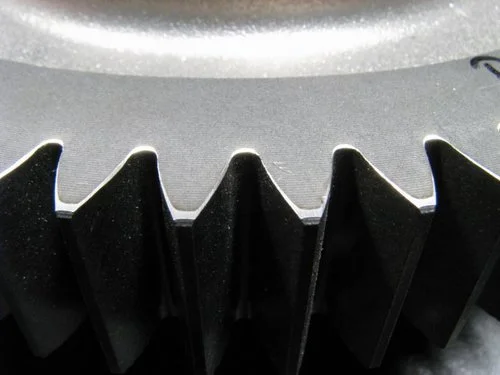
Champion of Gear Chamfers
Achieving the perfect chamfer can be frustrating, as there are so many factors that could cause an uneven chamfer. James Engineering offers a couple of tips on how to become the champion of chamfers.
Getting a perfect gear chamfer is not easy. In many cases, many people aren’t even aware that it could be done better; they probably don’t even know why they aren’t seeing better results.
There are many variables that affect the outcome of a chamfer: grinding wheel speed, grinding wheel pressure, grinding wheel angle, rotary table speed, etc. Keeping all these components in mind can be a headache! Who knew such a process could be so complicated?
Well, James Engineering has a couple of tips that will help you achieve the cleanest chamfer possible:
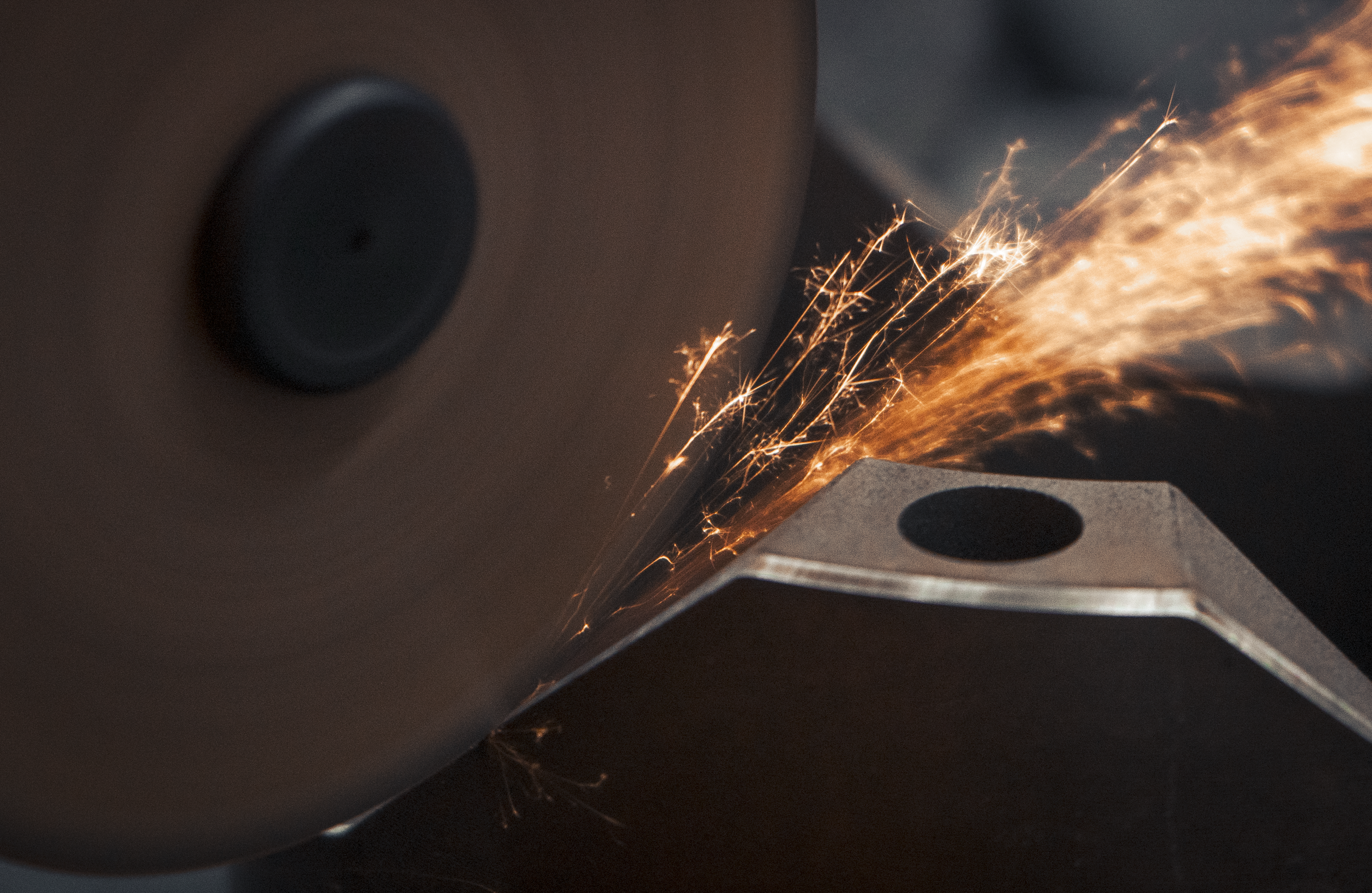
· Make sure the grinding wheel engages the part gently. If it’s too quick in engaging, you might notice a small cloud of dust burst up from the point of contact, gouging the part in a way that is noticeable to the eye. This small cloud will contain 3 to 4 times more material removed in that single instant than what you’d see after chamfering the entire part!
· Be sure that the grinding wheel produces an even spark pattern. Any interruption in that pattern is a loss in efficiency, and can be caused when the wheel lifts and bounces back down onto the part. Whether that bounce is subtle or extreme, it will still cause a decrease in wheel life and leave you with an inconsistent chamfer.
· To eliminate heavy chamfer marks, or what we call striations, use a wheel that has natural shock-absorption, such as the wheel we sell at James Engineering. Most companies use rigid cutoff wheels made of fiberglass reinforcing material, bonded with a dense (and usually black) open-cutting resin. But we at James Engineering suggest using a reinforced open-cutting, resin-bonded wheel with shock-absorbing properties, which also happen to be a lighter color and won’t break when forced to flex slightly. The best way to see the difference between the two kind of wheels, other than overall performance, is to bounce the cutting edge of the wheel off your desk. The competing wheel will bounce instantly, while ours will absorb some of the impact’s shock and not bounce as wildly—it’ll even sound quieter!
If you implement these three tips, chamfering becomes a whole different animal. You’ll be able to hear the difference between a good and bad chamfer; the good will sound smooth, while the bad will sound choppy. You’ll be left with a chamfer so clean, so perfect, you won’t be able to help but call it the champion of all gear chamfers. If you have any questions, or would like to receive a wheel sample, please feel free to contact us at Sales@James-Engineering.com.

Rough, uneven chamfers.

Smooth, even chamfers achieved by the MAX System, the ultimate gear chamfering machine